HI 800 101 HIMatrix Engineering Manual
3.3.1 Heat Dissipation
An enclosed case must be designed to allow the heat generated inside it to be dissipated
from its surface.
The type and site of installation must be selected to allow heat dissipation.
The heat output of the installed components determines the design of the ventilation compo-
nents. An even distribution of the heat load is assumed (see chapter
3.3.1.3).
3.3.1.1 Definitions
P
V
[W] heat output (heat dissipation) of the electronic components installed in the case
A [m
2
] effective surface area of case (see below)
k [W/m
2
K] heat transfer coefficient of case,
Steel sheet: ~ 5.5 W/m
2
K
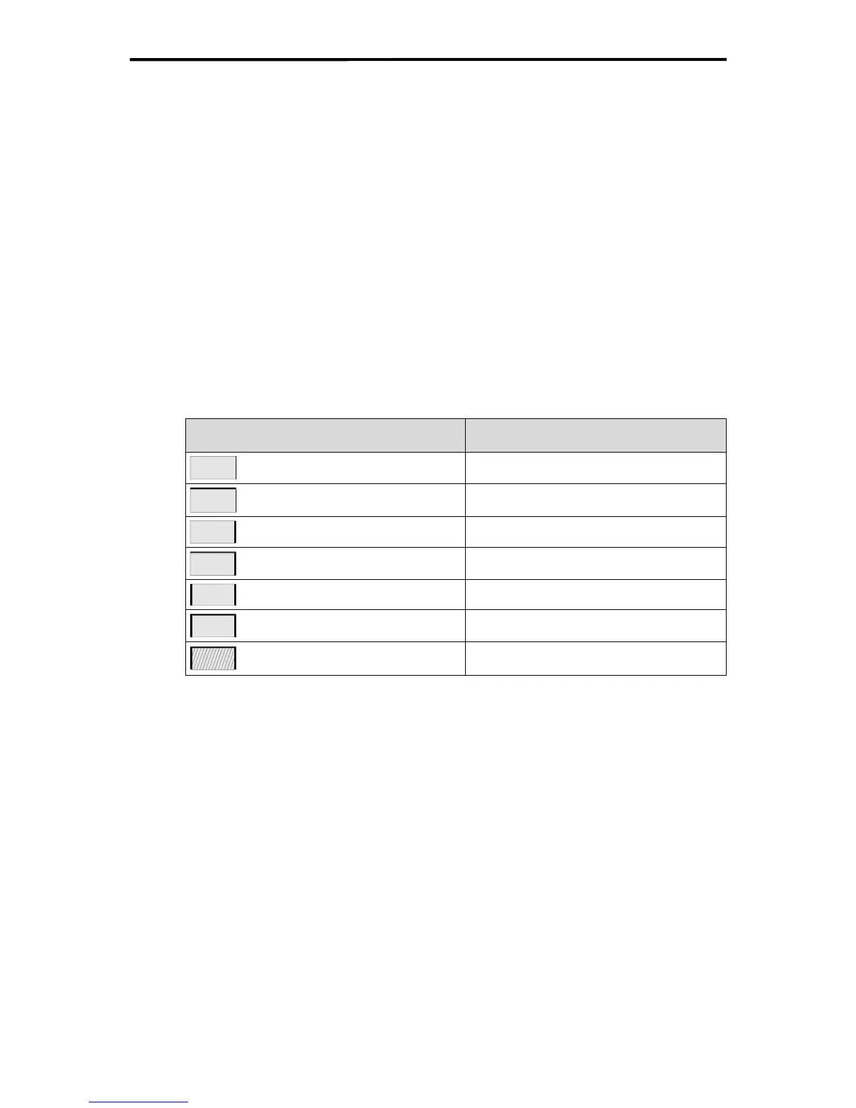
3.3.1.2 Installation Type
The effective case surface area A is calculated as follows depending on the mounting or in-
stallation type:
Case installation
according to VDE 0660 part 5
Calculation of A [m
2
]
Single case free on all sides A = 1.8 x H x (W + D) + 1.4 x W x D
Single case for wall mounting A = 1.4 x W x (H + D) + 1.8 x H x D
End case free-standing A = 1.4 x D x (W + H) + 1.8 x W x H
End case for wall mounting A = 1.4 x H x (W + D) + 1.4 x W x D
Centre case free-standing A = 1.8 x W x H + 1.4 x W x D + H x D
Centre case for wall mounting A = 1.4 x W x (H + D) + H x D
Centre case for wall mounting,
top surface covered
A = 1.4 x W x H + 0.7 x W x D + H x D
Table 2: Installation type
3.3.1.3 Internal Convection
With internal convection the heat is dissipated outside through the walls of the case. This re-
quires the ambient temperature to be lower than the temperature inside the case.
The maximum temperature increase (ΔT)
max
of all electronic devices in the case is calculated
as follows:
P
V
(
Δ
T)
max
= ———
k • A
The power dissipation P
V
can be calculated from the electrical power values of the controller
and its inputs and outputs.
15 of 61

 Loading...


