HI 800 101 HIMatrix Engineering Manual
4.5 Use in Central Fire Alarm Systems
All HIMatrix systems with analog inputs can be used for central fire alarm systems in accor-
dance with DIN EN 54-2 and NFPA 72.
The application program must fulfill the functions laid down for central fire alarm systems
according to the cited standards.
The required maximum cycle time of 10 seconds (DIN EN 54-2) for central fire alarm sys-
tems can easily be achieved with the systems as the cycle times of these systems can be
measured in milliseconds. Similarly, the required 1 second safety time (if necessary) can
also be easily achieved (error response time).
According to EN 54-2 the fire alarm system has to be in the fault report state within 100 sec-
onds after the HIMatrix system has received the fault report.
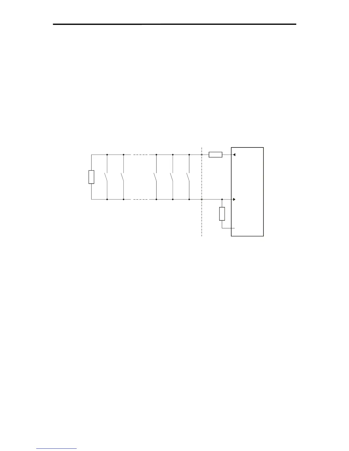
The fire alarms are connected using the energize to trip principle with Line Control for the de-
tection of short-circuits and breaks. The digital and analog inputs can be used with F35, the
analog inputs with F3 AIO 8/4 01 and the AI 8 01 analog input module with F60.
n
M
n-1
M
3
M
Shunt
R
1
M
2
M
L
R
EOL
R
Analog
input
Reference
pole (L-, I-)
Sensor
supply
Sensor Loop
Figure 4: Wiring of fire alarms
M Fire alarm
R
EOL
Terminating resistor on the last sensor in the loop
R
L
Limitation of the maximum permitted current in the loop
R
Shunt
Measuring resistor
For the application, the resistance of R
EOL
, R
L
and R
Shunt
should be calculated depending on
the sensors being used and the number of sensors per alarm loop. The required data is con-
tained in the relevant data sheet from the sensor manufacturer.
The alarm outputs, used for activating lamps, sirens, horns, etc, are operated using the
energize to trip principle. These outputs must be monitored for line breaks and short-circuits.
Feeding back the output signals directly from the actuator to the inputs can do this.
The current in the actuator circuit should preferably be monitored via an analog input with an
appropriate shunt. A series connection of zener diode and series protects the input against
overvoltage in case of short-circuit.
22 of 61

 Loading...


