HI 800 101 HIMatrix Engineering Manual
4 Configuring the Hardware
4.1 Supply Voltage
The HIMatrix system is a single voltage system. The required operating voltage is defined as
follows in accordance to IEC/EN 61131-2:
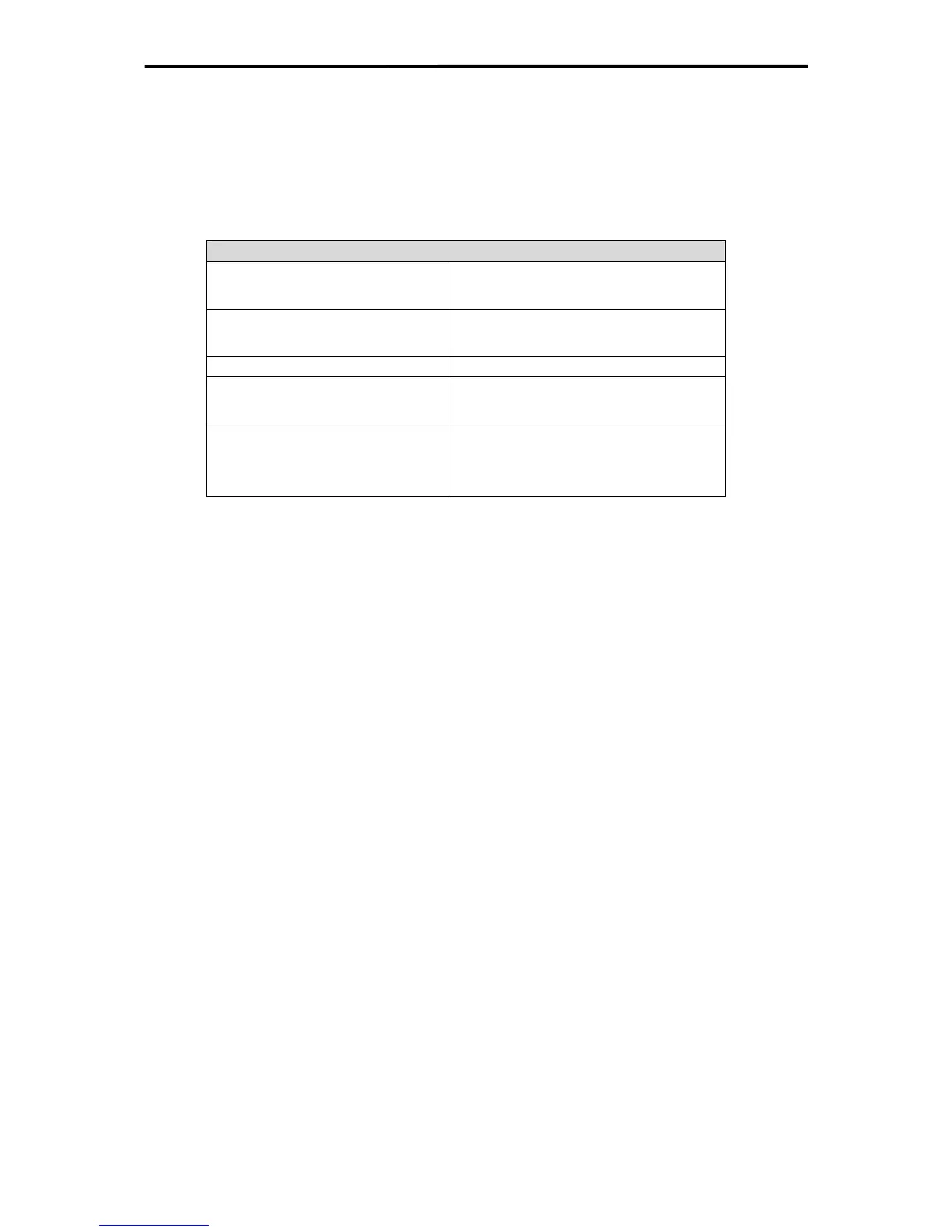
Supply voltage
Nominal value
24 VDC, -15...+20 %,
20.4 V...28.8 V
Max. permissible function limits in
continuous operation
18.5 V...30.2 V
(including ripple)
Maximum peak value
35 V for 0.1 s
Allowable ripple w < 5 % as r.m.s. value
w
ss
< 15 % as value peak-to-peak
Reference potential L- (negative pole)
Earthing the reference potential is per-
mitted (see chapter
3.5.1)
Table 4: Supply voltage
The HIMatrix controllers must be powered by power supply units that meet the requirements
of SELV (Safety Extra Low Voltage) or PELV (Protective Extra Low Voltage).
The controller will function correctly when the permitted voltage limits are maintained.
The specified SELV/PELV power supply units ensure secure operation.
4.2 De-energize to Trip Mode / Energize to Trip Mode
The programmable controllers are designed for the de-energize to trip mode.
The HIMatrix systems are certificated for process controllers, safety systems, burner sys-
tems and machine controllers.
A system operating according to the de-energize to trip mode does not need energy to per-
form its safety function.
In the event of a fault, the input and output signals revert to voltage-free or current-free sta-
tes to ensure safe operation.
The HIMatrix controllers can also be used in energize to trip mode applications.
A system operating according to the energize to trip mode needs energy, for example elec-
trical or pneumatic energy, to perform its safety function.
Therefore the HIMatrix F60, F35 and F3 AIO 8/4 01 were tested and certificated according to
EN54 and NFPA72 for use in fire alarm systems and fire extinguish systems. In these sys-
tems it is necessary that on demand the active state is used for controlling the danger (fur-
ther details see chapter
4.5).
19 of 61

 Loading...


