HI 800 101 HIMatrix Engineering Manual
Example: Calculation of power dissipation P
V
for controller F35
• Idle current consumption of the controller: 0.75 A at 24 V
• 8 outputs with current consumption of each 1 A at 2 V
• The current consumption of the digital inputs, analog outputs and counters can be
neglected.
Hence a maximum thermal power dissipation P
V
of approx. 34 W results.
3.3.1.4 Temperature State/Operating Temperature
The controllers are designed for operation up to a maximum temperature of 60 °C. The tem-
perature states of the single modules or the controllers are evaluated by the CPU module (at
F60) or the respectively installed CPU (compact systems) in the controller.
The temperature state of the particular module or the controller is measured by one tempera-
ture sensor in a relevant temperature location. This sensor monitors automatically and con-
tinuously the temperature state of the device.
The temperature state signals the measured temperatures in the following temperature ran-
ges:
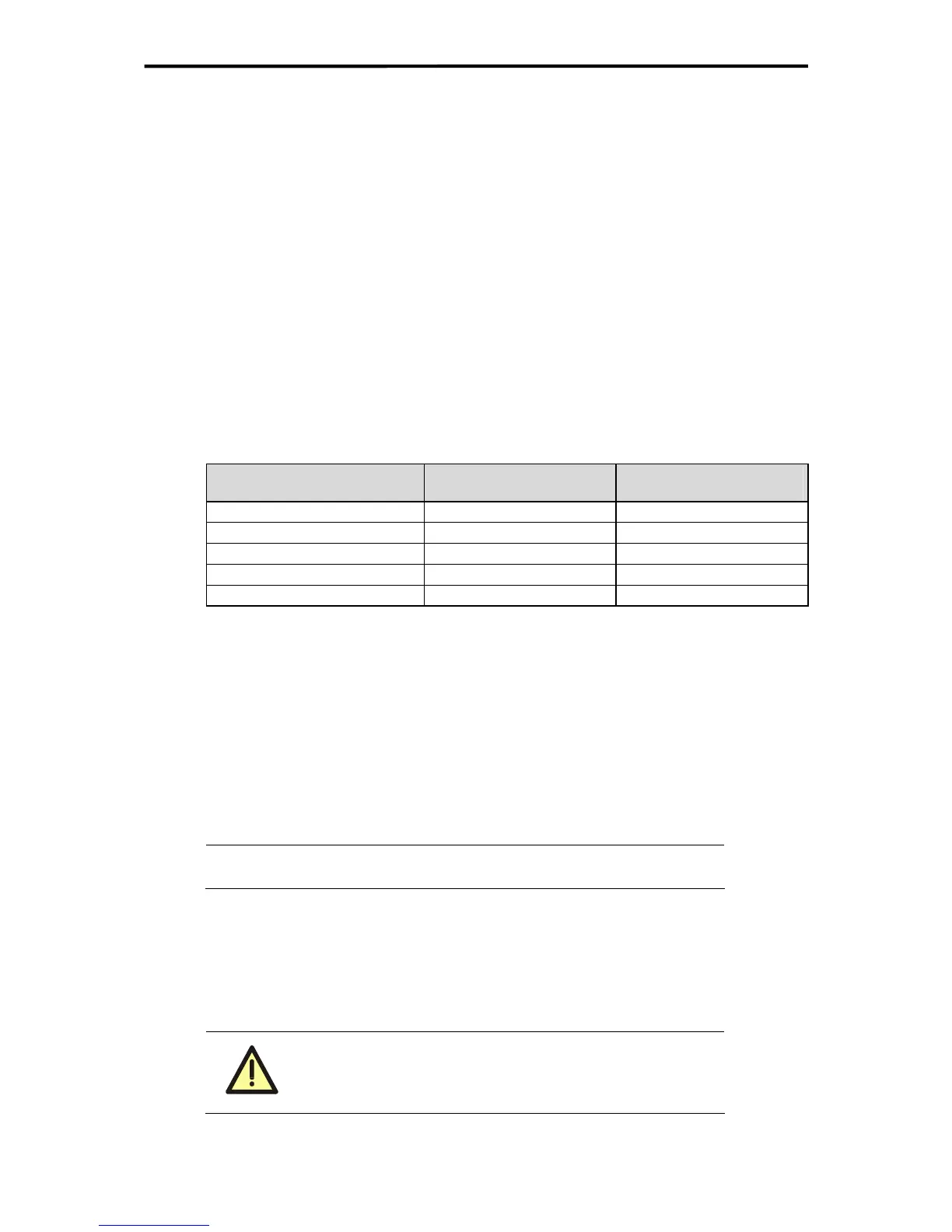
Temperature state Temperature range
Signal value [BYTE]
Temperature State
< 60 °C Normal 0x00
60 °C to 70 °C High temperature 0x01
> 70 °C Very high temperature 0x03
Return to 64 °C to 54 °C High temperature 0x01
Return to < 54 °C Normal 0x00
Table 3: Temperature state
If the temperature at a temperature sensor rises above a temperature threshold, the tem-
perature state changes.
The temperature states can be evaluated using the Temperature State system signal on a
programming unit running ELOP II Factory.
The display of the temperature state is carried out with a temperature hysteresis of 6 K.
3.3.1.5 Standard
The temperature in a case can also be calculated in accordance to VDE 0660 Part 507
(HD 528 S2).
Note
For heat contemplation all components in a housing have to be
regarded!
3.4 Operating Voltage
Before connecting the operating voltage of 24 VDC, check that the polarity is correct (see
also Chapter
4.1), otherwise the devices may be damaged.
The terminals L+ and L- may not be reversed!
A pre-fuse prevents damages in case of wrong polarity!
Damage may also be caused by connection with other ter-
minals of the PES.
16 of 61

 Loading...


