HI 800 101 HIMatrix Engineering Manual
Configuring a network with switches ("Switched Ethernet") has the following advantages:
• Very fast packet transfer between the collision areas,
• Significant increase of data throughput with full-duplex mode,
• Prevention of collisions allows deterministic operation.
5.4.1.1 Interface Elements
When connecting a controller to the Ethernet communication, interface elements, such as
the
FL CAT5 TERMINAL BOX (manufacturer Phoenix Contact
®
)
type, can be used in the control cabinet. They are mounted on an earthed EN mounting rail.
The conductors of the field cable are attached to the interface terminals in the control cabi-
net. It is important to make sure that the cable shield is also connected via the strain relief.
Prefabricated patch cables are used to connect the interface element and the HIMatrix con-
troller.
In the case of the interface element mounting it on the rail is sufficient for earth connection,
as long as the rail itself is earthed in accordance to the standard.
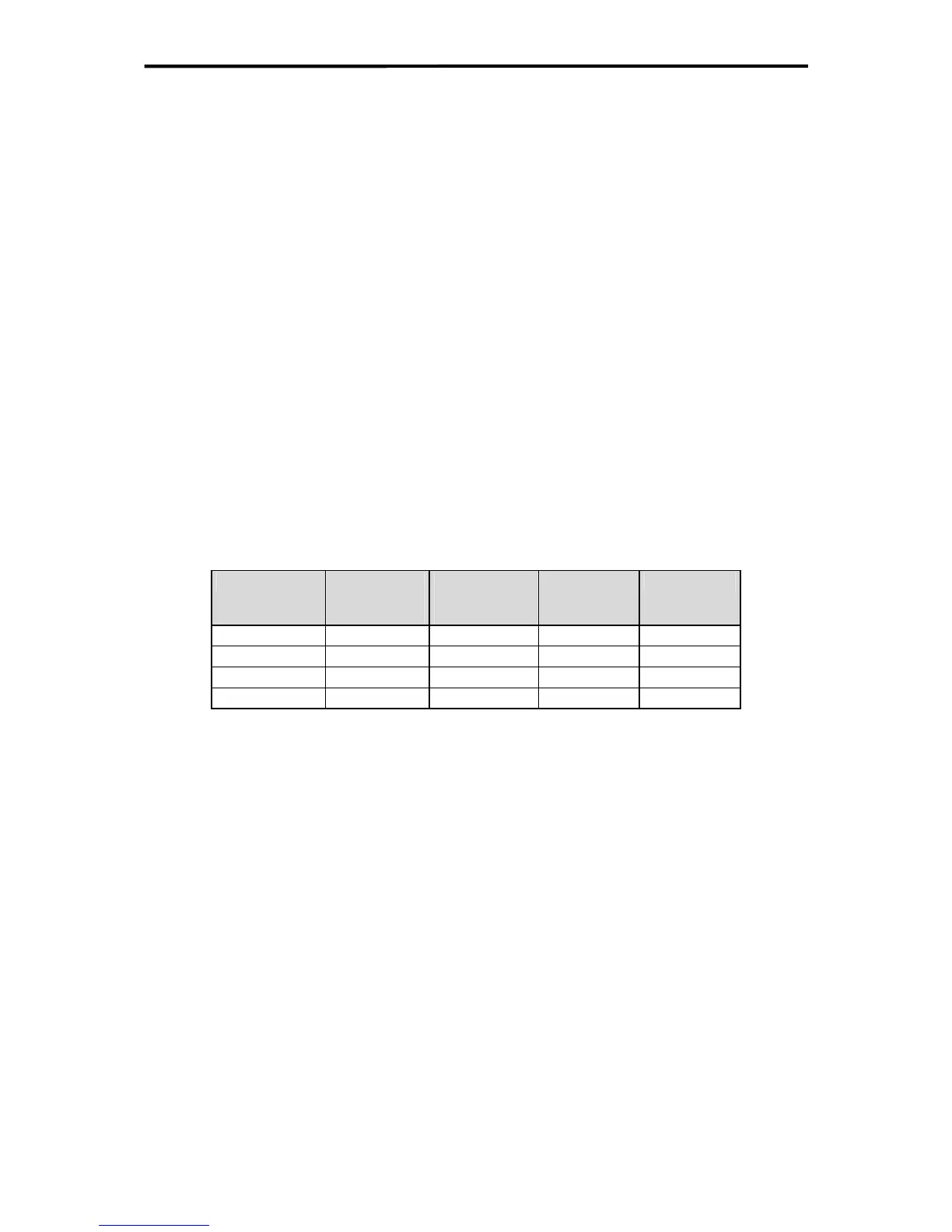
5.4.1.2 Specified Cables
For Ethernet communication in HIMatrix systems at 100 MHz Category 5 (or better) cables
and at least Class D capacity are required.
Cable specifications CAT 5
Frequency
Attenuation
per 300 m
cable length
Resistance
per 300 m
cable length
Capacitance Impedance
4 MHz 13 db 28,6 Ω 42 pF/m 100 Ω
10 MHz 20 db 28,6 Ω 42 pF/m 100 Ω
20 MHz 28 db 28,6 Ω 42 pF/m 100 Ω
100 MHz 67 db 28,6 Ω 42 pF/m 100 Ω
Table 9: Cable specifications CAT 5
The maximum cable length at UTP/STP with category 5 (CAT5) is typically:
• 100 m between network interface and hub/switch
• 100 m between two network interfaces (two computers connected with crossover
cable)
35 of 61

 Loading...


