HI 800 101 HIMatrix Engineering Manual
7.4.1.2 Line Monitoring with Reduced Voltage for Resistive, Capacitive Loads
For line monitoring a 10 V signal is switched on in the output circuit for the duration of the
monitoring time. This kind of line monitoring is designed for resistive or resistive capacitive
loads. At inductive loads or lamp loads there can be error messages concerning
short-circuit.
For configuration of line monitoring the following signals must be set in ELOP II Factory
Hardware Management:
DO.LSLB period Value adjustable (1 to 100 seconds)
DO.LSLB time Value adjustable (0 to 50 ms, default: 0 ms)
DO[xx].2-pole set on TRUE
DO[xx].LSLB monitoring set on TRUE
DO[xx].LS monitoring with reduced voltage set on TRUE
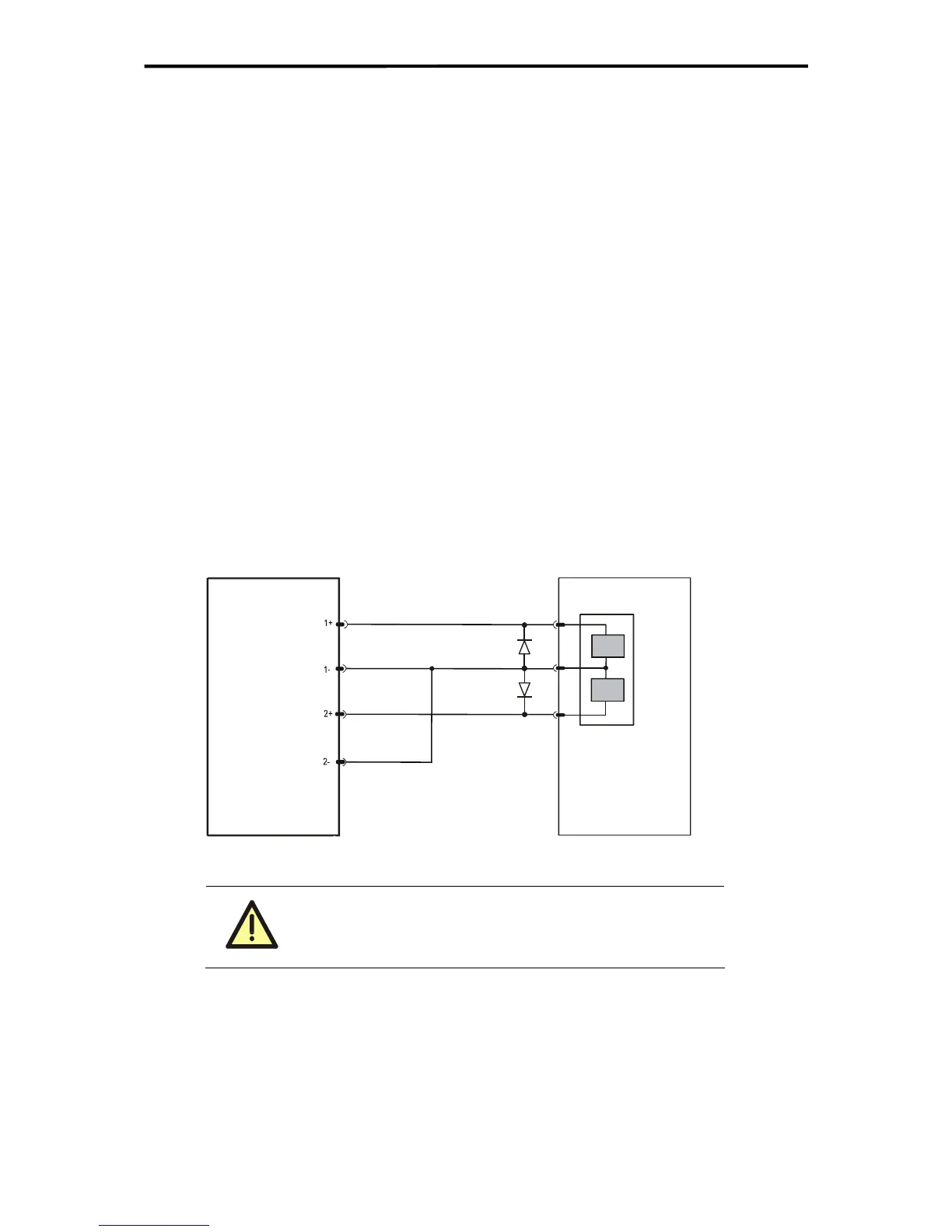
7.4.1.3 2-Pole Connection with Common Reference Pole (3-Pole Connection)
Two 2-pole channels are connected to a common reference pole to realize a line monitoring
at motor drives (2 coils), valves etc.. Therefore the system signal DO[xx][xx].in pairs for
each pair (2 channels) must be parameterized (further configurations see also
Table 20:
Configuration possibilities of digital outputs
). If line monitoring is set on both channels with
DO[xx].LSLB monitoring = TRUE, the line monitoring is carried out on both 2-pole chan-
nels in pairs (channel 1 and 2, channel 3 and 4, channel 5 and 6, channel 7 and 8). During
line monitoring on first channel the second channel will be switched off to prevent any falsifi-
cation of the line monitoring.
A short-circuit between the both DO+ lines is not checked.
A detected line fault is reported by a system signal (DO[xx].+Error Code or DO[xx].
-Error Code).
F3 DIO 16/8 01
(drive, valve)
Load
Figure 34: 2-pole connection with common reference pole (3-pole connection)
Inductive loads must be connected with a protection diode
on the load.
54 of 61

 Loading...


