HI 800 101 HIMatrix Engineering Manual
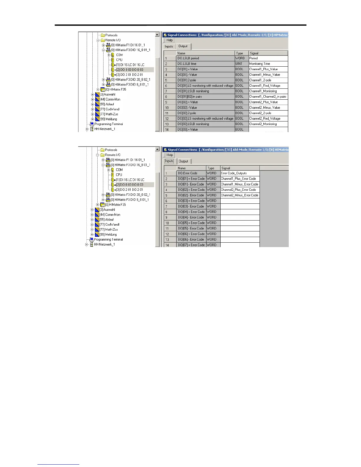
Figure 32: Setting the parameters for line monitoring (Outputs F3 DIO 16/8 01)
Figure 33: Setting the error codes for the outputs (Inputs F3 DIO 16/8 01)
For monitoring the outputs for each channel two error codes (DO+ and DO- output,
DO[xx].+Error Code and DO[xx].-Error Code) can be evaluated. The whole output module is
monitored via the signal DO.Error Code.
7.4.1.1 Line Monitoring for Lamp Loads and Inductive Loads
For short-circuit detection a 24 V impulse with a duration of 500 µs is switched in the output
circuit. Afterwards a 10 V signal is set for the duration of the monitoring time to detect a line
break.
For configuration of line monitoring the following signals must be set in ELOP II Factory
Hardware Management:
DO.LSLB period Value adjustable (1 to 100 seconds)
DO.LSLB time Value adjustable (0 to 50 ms, default: 0 ms)
DO[xx].2-pole set on TRUE
DO[xx].LSLB monitoring set on TRUE
DO[xx].LS monitoring with reduced voltage set on FALSE
53 of 61

 Loading...


