HI 800 101 HIMatrix Engineering Manual
Signal name
Type
Description
Default
value
DO[01][02].in pairs
BOOL
Couple of common reference
(DO- outputs build common reference potential)
Couple 1 = Channel 1 [01] and channel 2 [02]
DO[01][02].in pairs=1
0
DO[01].LS
monitoring with
reduced voltage
BOOL
Line monitoring with reduced voltage channel1
1 = reduced signal voltage level
0 = normal signal voltage level
(reduced signal voltage level only active with
signal DO[xx].LSLB Monitoring =1!)
0
DO[02].LS
monitoring with
reduced voltage
BOOL
Line monitoring with reduced voltage channel2
1 = reduced signal voltage level
0 = normal signal voltage level
(reduced signal voltage level only active with
signal DO[xx].LSLB Monitoring =1!)
0
Table 19: Signals for line monitoring 2-pole
The system signals listed above (software) must be defined at first in the Signal Editor and
then assigned to the hardware channels of the digital outputs (register "inputs" and register
"outputs"). The principle method of signal assignment is described in chapter
7.2.3.1. During
assignment you have to regard the identical data types of signal and hardware channel.
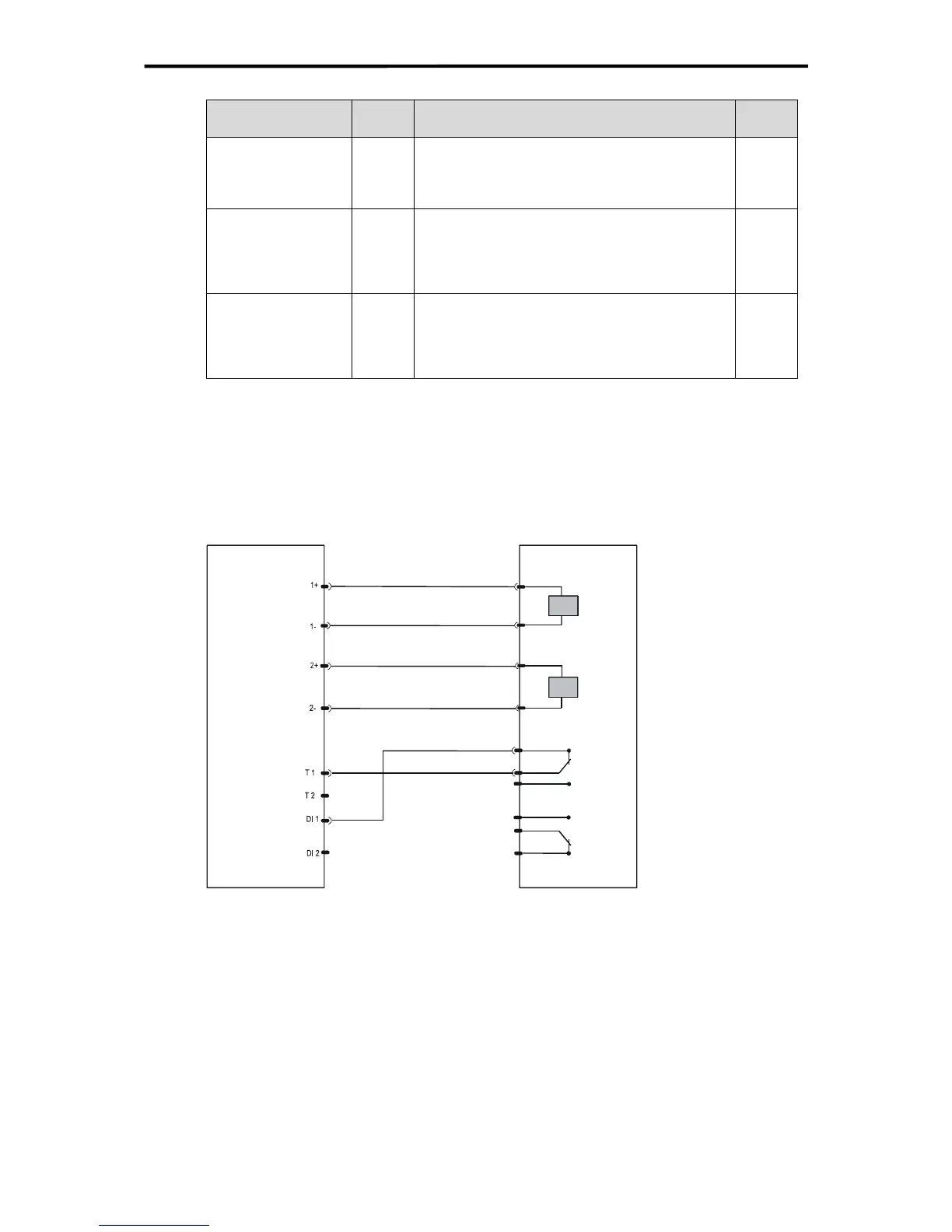
In the following scheme the principle wiring possibility of a 2-pole connection is shown:
F3 DIO 16/8 01
Load
(drive, valve)
Figure 31: 2-pole connection of digital outputs with Line Control of digital inputs
Beside the line monitoring of the digital outputs switching contacts can be monitored for
short-circuit and line break by pulsing the digital inputs (Line Control, see chapter
7.1).
52 of 61

 Loading...


