HI 800 101 HIMatrix Engineering Manual
DI [07] could have used T1 and DI [08] correspondingly T2.
The allocation depends on the hardware configuration.
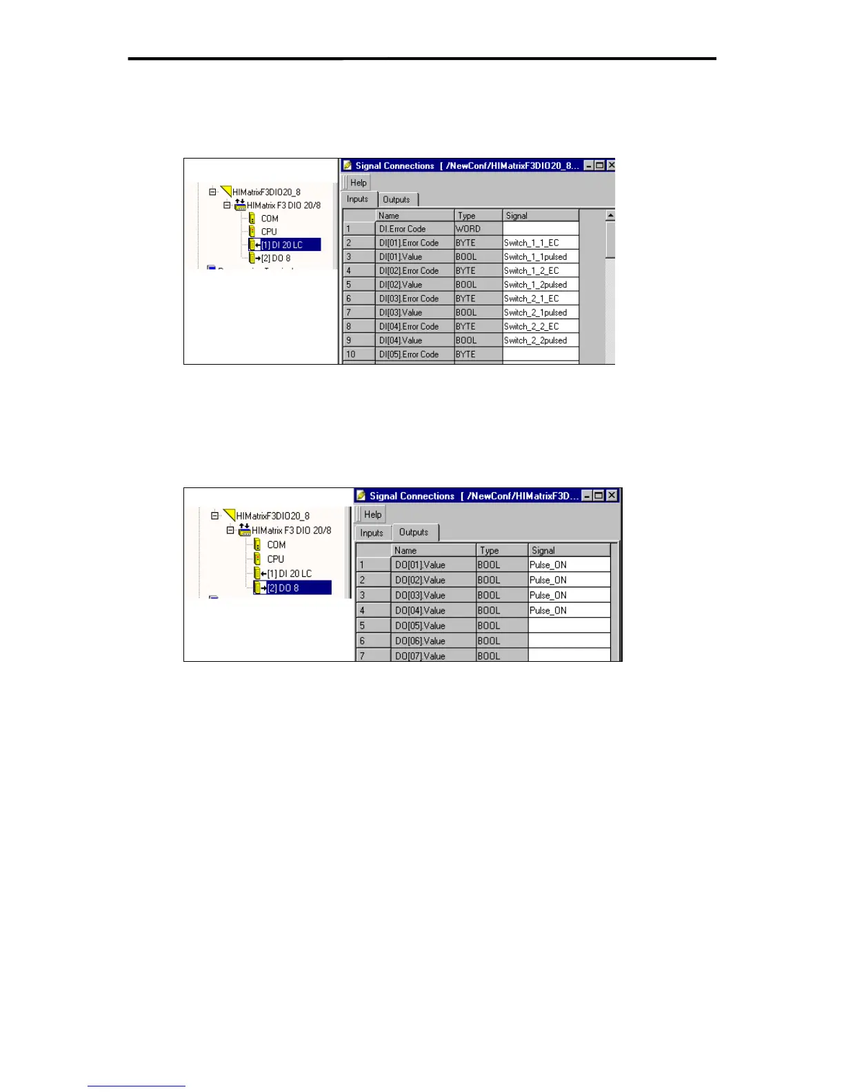
7.2.3.3 Assignment of the Signals to the Inputs and their Error Codes
Figure 24: Assignment of the Signals to the Inputs and their Error Codes
The relevant error code must also be evaluated for every usable signal DI[xx].Value.
7.2.3.4 Activation of the Pulsed Outputs
Figure 25: Activation of the pulsed outputs
The logical value of the signal Pulse_ON is TRUE. This keeps the pulsed outputs continu-
ously activated and they are only set to FALSE for the duration of the pulse actuation.
7.3 Line Monitoring at HIMatrix F35
The following shows an example how line break and short-circuit detection can be realized
with the digital inputs (contacts) of a HIMatrix F35 system.
The F35 system contains 3 groups of 8 digital inputs. Each digital input has beside the boo-
lean value (not needed in this application) an analog value with 0 ... 3000 digits (= 0 ... 30 V)
which is used to determine line break, short-circuit, HIGH and LOW state.
Each group is feeded by its own LS+. Since the voltage of this LS+ depends on the load and
the power supply voltage it is recommendable to spend one digital input per group to meas-
ure the voltage of the LS+ and to calculate the limits for line break, short-circuit, HIGH and
LOW state dynamically.
The example shows the calculation and realization for LB and SC detection for a contact
parallel to a 6000 Ohm resistor which is in series to a 3900 Ohm resistor. The resistors have
a tolerance of 1%.
46 of 61

 Loading...


