HI 800 101 HIMatrix Engineering Manual
7.2.3 Configuration Example
7.2.3.1 Principle Method of Signal Assignment
With the use of the software ELOP II Factory the previously via signal editor defined signals
(hardware management) could be assigned to the single existing hardware inputs and out-
puts.
Follow the further steps in ELOP II Factory Hardware Management:
Open Signal Editor in menu Signals.
Right-click on the HIMatrix I/O module and select Connect Signals in the context menu.
A new window opens for allocating the logic signals of the Signal Editor to the existing
hardware signals, i.e. the inputs and outputs (different registers).
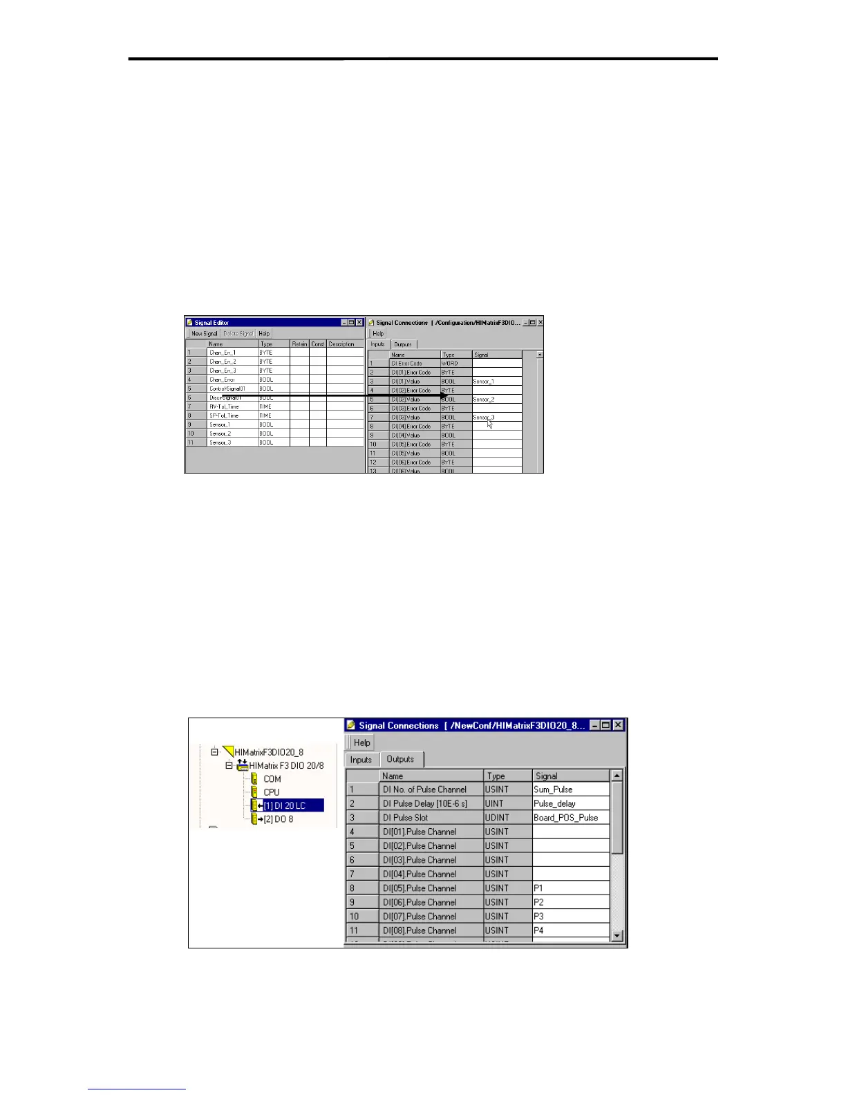
Figure 22: Drag & drop allocating of signals to the inputs (principle scheme)
For better overview you can tile both windows of Signal Editor and Signal Connections
side by side.
In the Signal Editor click on a signal name and drag the signal into the "Signal" column
(used channel, input) of the "Signal Connections" window.
For signal connection of the outputs change the register to "Outputs" and do in the same
way as for the inputs.
In the following configuration example the list of the signal editor in 6.1.1 is used practicing
the method described above.
7.2.3.2 Configuring the Pulsed Outputs and Assignment to the Inputs
Figure 23: Configuring the pulsed outputs and assignment to the inputs
The assignment of the digital inputs (pulse channels) to the pulsed output channels is arbi-
trary.
45 of 61

 Loading...


