HI 800 101 HIMatrix Engineering Manual
The FAULT LED on the front panel of the controller flashes, the inputs are set to 0-signal
and an (analyzable) error code is generated if the following errors occur:
• Cross connection between two parallel lines,
• Change of two lines DO to DI, connection against the preset configuration in the
software, e.g. DO 2 → DI 7 (configured), DO 2 → DI 6 (wired),
• Earth fault of one of the conductors (with earthed reference pole only),
• Line break or opening of contacts, i.e. the LED "FAULT" also flashes and the error
code is generated if one of the above EMERGENCY OFF switches is actuated.
Note
If multiple errors are existing at the same time, the error code is
the sum of the codes of the individual errors.
The pulse delay for the Line Control is the time between writing the pulsed outputs to FALSE
and the latest possible reading of the signal at the relevant input. The default value is set to
400 μs. It may be necessary to increase this with longer cables. The maximum value is
2000 μs.
The minimum time for reading all inputs results in pulse delay x number of pulses.
The pulsed outputs are permanently set to TRUE. In each cycle the pulsed outputs will be
set successively to FALSE for the duration of the pulse delay.
7.2.1 Required Signals
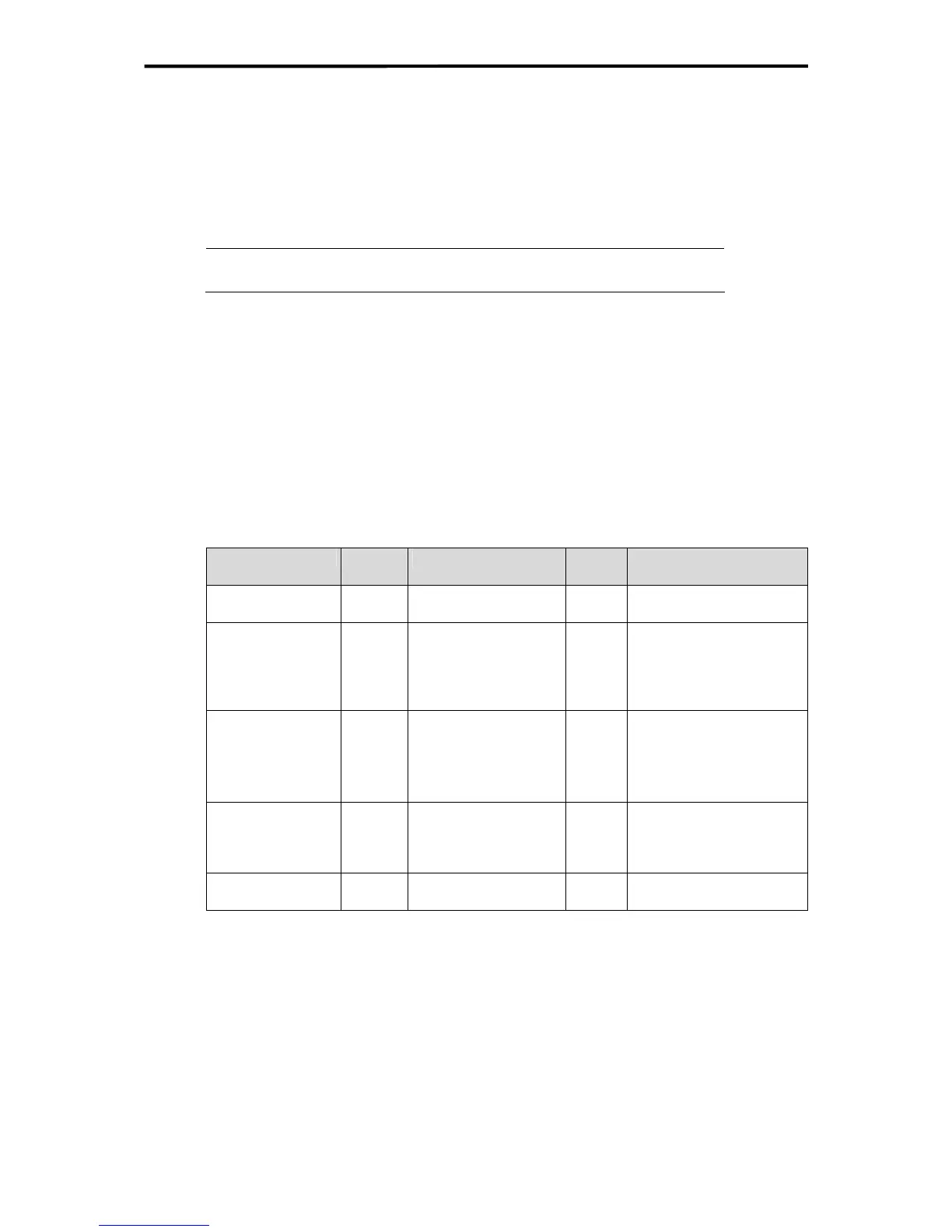
The following signals must be set up in the ELOP II Factory Hardware Management:
Signal name Type Description Initial
value
Remarks
Sum_Pulse USINT Number of pulsed
outputs
4
1...8, as required
Board_POS_Pulse UDINT Slot of module with
the pulsed outputs
2 In the compact devices
the DOs are in slot 1,2 or
3 (see
Table 16).
In the F60 the slot (1...6)
is specified.
Pulse_delay UINT Pulse delay 400 Value in µs
Maximum value: 2000 µs
F20: Pulse delay must be
≥ 500 µs.
See datasheet of the F20.
P1
P2
...
P8
USINT
USINT
...
USINT
Pulse 1
Pulse 2
...
Pulse 8
1
2
...
8
Pulse 1 to pulse 8, as
required, must match the
number of pulsed outputs
Pulse_ON BOOL Initialization value for
the pulsed outputs
TRUE Activation of pulsed out-
puts
Table 14: Signals for Line Control
The signal names can be freely selected; the names used here are examples. All signals ha-
ve the attribute "Const".
43 of 61

 Loading...


