HI 800 101 HIMatrix Engineering Manual
RS
RP
RL
LS1+
DI1
DI2
DI8
RI
RI
RI
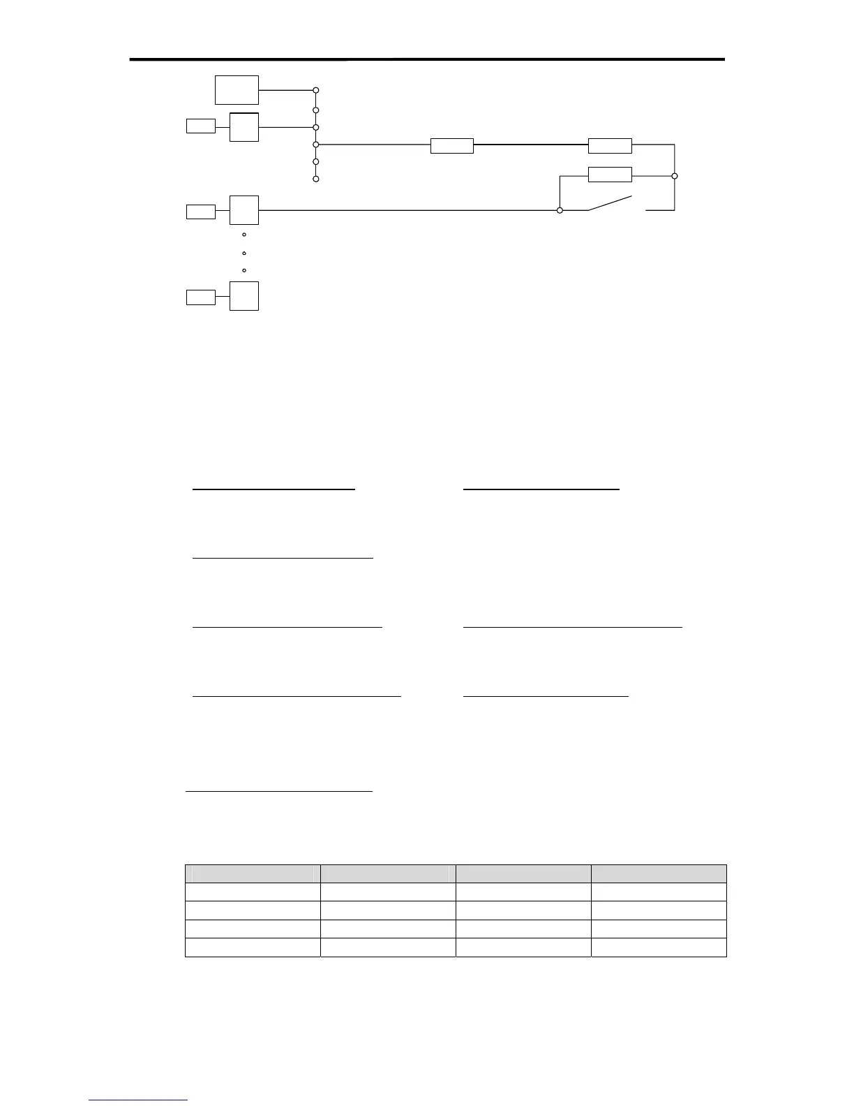
Figure 26: Scheme for Line Monitoring at F35
RP = resistor parallel to the contact (= 6000 Ohm in this example)
RS = resistor in series to the contact and RP (= 3900 Ohm in this example)
RL = wiring resistance (= 0 Ohm in this example)
RI = input resistance of digital input = 6900 Ohm
DI = digital input
LS1+ = feeding for digital inputs (group 1)
Input Voltage for Line Break
Ulb = 0 V
Input Voltage for Open Contact
Uoc = RI*LS+ / (RL + RS + RP + RI)
Input Voltage for Closed Contact
Ucc = RI*LS+ / (RL + RS + RI)
Input Voltage for Short Circuit (field)
Usc = RI*LS+ / (RL + RI)
Limit for Line Break (digits)
Line break < 200 = 2 V
Limit for Open/Closed Contact (digits)
Closed Contact > (Ucc - Uoc) / 2 + Uoc
Limit for Short Circuit (digits)
Open Contact < (Ucc - Uoc) / 2 + Uoc
Short Circuit > (Usc - Ucc) / 2 + Ucc
Example values for calculations:
RP = 6000 Ohm / RS = 3900 Ohm / RL = 0 Ohm / RI = 6900 Ohm
LS+ = 18V / 21,5 V / 24 V
LS+ = 18 V LS+ =21.5 V LS+ = 24 V
Ulb [digit] 0 0 0
Uoc [digit] 740 883 986
Ucc [digit] 1150 1374 1533
Usc [digit] 1800 2150 2400
Table 18: Input voltages Uxx at different feeding voltages LS+
47 of 61

 Loading...


