HI 800 101 HIMatrix Engineering Manual
The table shows that the gaps between Ulb, Uoc, Ucc and Usc increase with a rising voltage
for LS+. In this example 18 V is considered as the worst case for LS+ (this value will be
monitored in the logic) and the gaps between Ulb, Uoc, Ucc and Usc are sufficient to differ
the several cases which can occur.
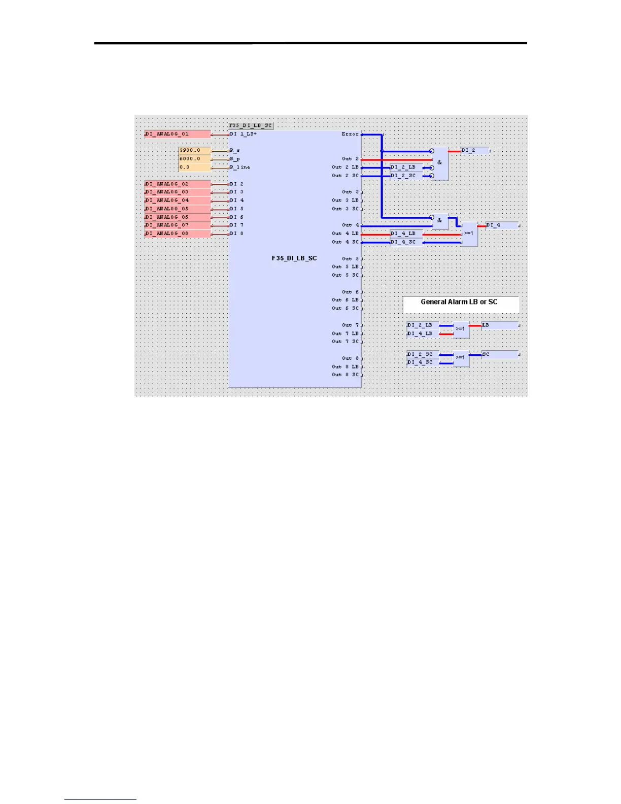
Figure 27: Function block for Line Monitoring at F35
The picture above shows a function block, which could be used to monitor, detect and define
the reaction to line break and short circuit.
The DI2 is only in HIGH state (good state), when there is no error (e.g. LS+ < 18V), no line
break, no short-circuit and when the contact is closed.
DI4 shows an example for an application which requires that there is no reaction in case of
line break or short circuit.
Additionally there are general signals built for line break and short-circuit.
The parameter R_line, which is representing the wiring resistance, is used for all 7 loops.
If using this parameter an average-value for the loop resistances should be used.
48 of 61

 Loading...


