14
Part Names and Functions
1.3 Part Names and Functions
Front
1
2
3
4
5
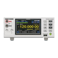
1 Display
(Touch panel)
Viewmeasuredvalues,settings,andjudgmentresults;congureinstrumentsettings.
• Display the Settings screen and Measurement screen (measured values and judgment
results) (p. 16).
• Congure settings (p. 17).
2 Operation
keys
For more information: See
“1.5OperatingtheInstrument”(p. 17).
[V/°C]
key
Toggles display of
temperature measured
values.
[AUTO]
key
Enables auto-range
operation (to automatically
select an appropriate range).
[NULL]
key
Adjusts the instrument’s
zero-point.
[RANGE]
[
]
key
Increases the range (to
measure high voltages).
[RUN/STOP]
key
Starts and stops
measurement.
[
]
key
Decreases the range (to
measure at a higher degree
of resolution).
[TRIG]
key
Starts measurement (to
make measurements at
the desired timing).
[SPEED]
key
Changes the measurement
speed.
3 POWER
button
(p. 28)
Switches the instrument’s
power state.
OFF: The instrument is off (no power is being supplied).
RED:
The instrument is in the SLEEP state (power is
being supplied).
GREEN: The instrument is on.
4
USBashdrive
connector
Outputsmeasurementdata,screendata,andmeasurementconditions;loads
measurement conditions (p. 115).
5 Voltage
measurement
terminals
Connect the measurement
cables (p. 26).
HIGH terminal: Connect the red cable.
LOW terminal: Connect the black cable.
See “Before connecting a measurement cable”(p. 9).
Bottom
Foot
Foot
Whenmountingtheinstrumentinarack
Be sure to collapse the feet all the way.
See: “Appx. 7 Rack Mounting” (p. Appx.14)
When using the feet
Be sure to:
• Open the feet all the way, without stopping partway.
• Erect both feet.
w ww . . co m
information@itm.com1.800.561.8187
 Loading...