Appendix 7 Unstable Measured Values
A17
Appendix
(4) Wider/Thicker measurement targets
When the measurement target is wide or thick like a
board or block, or when using a current sensing
resistor (shunt resistor) of less than 100 m, it will
be difficult to measure accurately using Pin Type
Leads or Clip Type Leads. By using such measure-
ment probes, there may be considerable fluctuation
of the measured value due to contact pressure or
contact angle. For example, when measuring a
W300 × L370 × t0.4 mm metal board, the measured
values are fairly different, even if measuring the
same points, as shown below:
• 0.2mm pitch Pin type lead: 1.1 m
• 0.5mm pitch Pin type lead: 0.92 to 0.97 m
• Model L2101 Clip Type Lead: 0.85 to 0.95 m
Additionally, since the resistance values of current sensing resistors assume mounting on a
printed circuit board, the desired resistance value cannot be obtained if the resistor’s termi-
nals are measured using a pin-type lead.
This does not depend on the contact resistance between
probe
s and the measurement tar-
get, but on the current distribution on the measurement target.
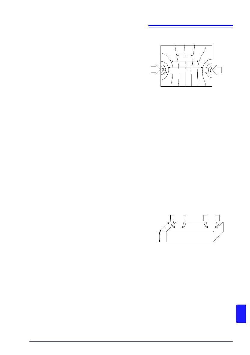
Fig. 10 is an example of plotting equivalent electric potential lines of a metal board. Similar
to the relation between atmospheric pressure distribution and wind on a weather forecast
diagram, current density is higher in locations where the equivalent electric potential lines
are narrowly spaced, and lower in locations where they are widely spaced. Through this
example, it is shown that the electric potential slope is larger around current applying
points. This phenomenon is caused by high current density while current expands on the
metal board. Due to this phenomenon, measured values should be rather different, even if
the connected position difference is quite slight, in case connecting voltage detection termi-
nals (of measurement
probe
s) near current applying points.
It is known that such effects can be minimized by
detecting the voltage within the space between the
current contact points.
Generally, if the probes are inside by a margin that is
at least three times the measurement target’s width
(W) or thickness (t), current distribution may be con-
sidered uniform.
As shown in Fig. 11, SENSE leads should be 3W or
3t mm or more inside from the SOURCE leads.
(5) Unstable Temperature of the measurement target
Copper wire resistance has a temperature coefficient of about 0.4%/°C. Just holding a cop-
per wire in the hand raises its temperature, causing its resistance to be increased as well.
When the hand is removed from the wire, temperature and resistance decrease.
Windings are more susceptible to temperature increase immediately after treatment with
varnish, so the resistance tends to be relatively high.
When the temperature of the measurement target and probe differ, thermal EMFs will be
generated, causing an error. Allow the measurement target to adjust to room temperature
as much as possible prior to measurement.
Current
Applying
Figure 10. Equipotential lines on a metal
board (W300 × L370 × t0.4 mm)
∗ Applying 1 A current on points on edges
and plotting equivalent electric potential
lines at each 50 V level
0.1m
0.2m
0.3m
0.4m
3W, 3t or more 3W, 3t or more
Figure 11. Probe Positions on
Wider/Thicker measurement target
SOURCE B SENSE B SENSE A SOURCE A
W
t