8.1 External Input/Output Connector and Signals
91
8
Before connecting a connector, see "Before Connecting EXT I/O" (p. 11). Use of EXT I/O
enables the following control functionality:
• Measurement start (TRIG) Measurement end (EOM, INDEX)
Acquisition of judgment results (HI, IN, LO, ERR)
• Measurement start (TRIG) Measurement end (EOM, INDEX)
Acquisition of measured values (BCD_LOW, BCDm_n, RNG_OUTn)
• Panel load (LOAD0 to LOAD3, TRIG)
• General-purpose I/O (IN0, IN1, OUT0, OUT1, OUT2)
The functionality described in "Performing an I/O Test (EXT I/O Test Function)" (p. 117)
provides a convenient way to check external I/O operation.
Connector Type and Signal Pinouts
Pin Signal name I/O Function Logic Pin Signal name I/O Function Logic
1
TRIG
IN0
IN
External trigger
General-pur-
pose input
Edge 20 0ADJ IN Zero adjust Edge
2 BCD_LOW IN
BCD
Lower byte
output
Level 21 (Reserved) - - -
3 KEY_LOCK IN Key-Lock Level 22 LOAD0 IN Panel load Level
4 LOAD1 IN Panel load Level 23 LOAD2 IN Panel load Level
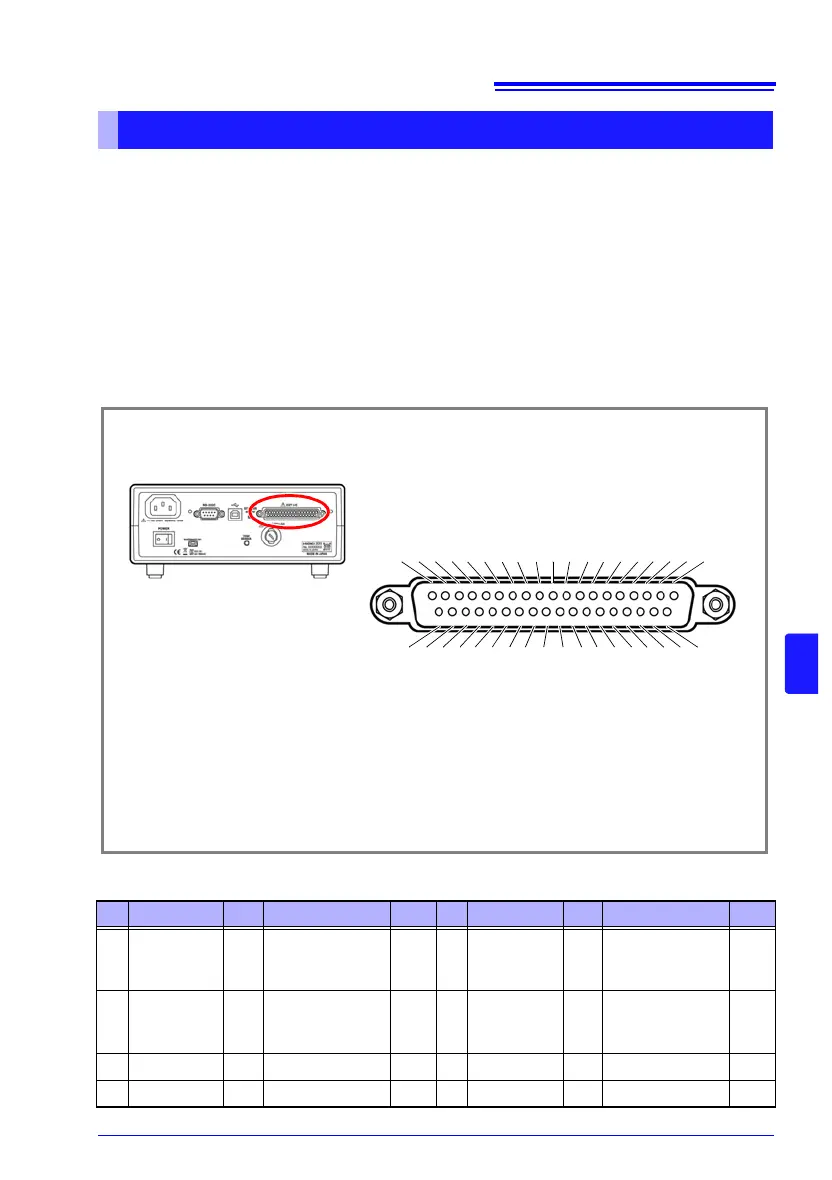
EXT I/O Connector (Instrument Side)
Connector: (Instrument Side)
37-pin D-sub female with #4-40 screws
Mating Connectors:
DC-37P-ULR (solder type) /
DCSP-JB37PR (pressure weld type)
Japan Aviation Electronics Industry Ltd.
12345678910111213141516171819
202122232425262728293031323334353637
TRIG, IN0
BCD_LOW
KEY_LOCK
LOAD1
LOAD3
(Reserved)
(Reserved)
ISO_5V
ISO_COM
ERR
HI, HILO
LO, BCD2-1, RNG_OUT1
BCD2-3, RNG_OUT3
BCD3-1
BCD3-3
BCD4-1
BCD4-3
OUT0, BCD5-1, BCD1-1
OUT2, BCD5-3, BCD1-3
0ADJ
(Reserved)
LOAD0
LOAD2
(Reserved)
(Reserved)
PRINT, IN1
ISO_COM
EOM
INDEX, BCD2-0, RNG_OUT0
IN
BCD2-2, RNG_OUT2
BCD3-0
BCD3-2
BCD4-0
BCD4-2
BCD5-0, BCD1-0
OUT1, BCD5-2, BCD1-2