Network Load Control
UM Basic Configuration L3P
Release
7.1
12/2011
8.6
VLANs
195
Example 2
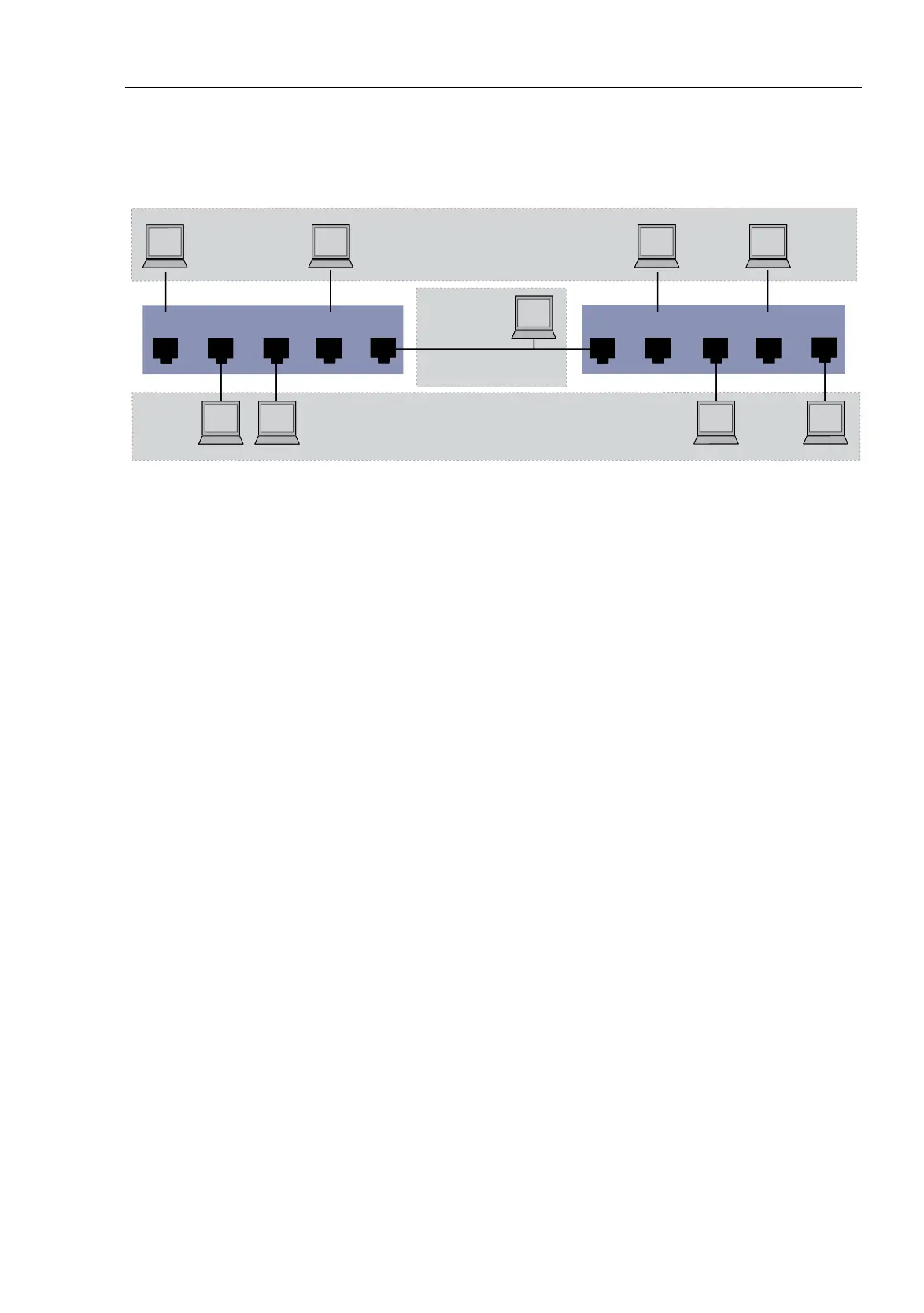
Figure 45: Example of a more complex VLAN configuration
The second example shows a more complex configuration with 3 VLANs
(1 to 3). Along with the Switch from example 1, you use a 2nd Switch (on
the right in the example).
The terminal devices of the individual VLANs (A to H) are spread over 2
transmission devices (Switches). Such VLANs are therefore known as
distributed VLANs. An optional Management Station is also shown, which
enables access to all network components if the VLAN is configured
correctly.
Note: In this case, VLAN 1 has no significance for the terminal device
communication, but it is required for the administration of the transmission
devices via what is known as the Management VLAN.
As in the previous example, uniquely assign the ports with their connected
terminal devices to a VLAN. With the direct connection between the two
transmission devices (uplink), the ports transport packets for both VLANs.
To differentiate these you use “VLAN tagging”, which handles the frames
accordingly (see on page 169 “VLAN tagging”). The assignment to the
respective VLANs is thus maintained.
Proceed as follows to perform the example configuration:
Add Uplink Port 5 to the ingress and egress tables from example 1.
Create new ingress and egress tables for the right switch, as described in
the first example.
132
VLAN
2
VLAN
3
A
BC
D
1432
E
FH
G
4
5
5
Management
Station (optional)
VLAN 1
 Loading...