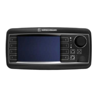
Description of the System
© 2016 Hirschmann Automation and Control GmbH · Mobile Machine Control Solutions · www.beldensolutions.com 10/161
qSCALE i2 Cranes (Tool Version 3.0.34) Service Manual / Issue B / 11-2017 / ac.
2.1.2 Description of the CAN Bus System
CAN stands for “Controller Area Network” and is intended to be used as a serial bus system for a net-
work of controllers. Each controller connected through a CAN chip is called a "node" and is mostly used
to acquire data from a sensor. All nodes are connected to a common bus and all nodes are able to
simultaneously read the data on that bus. Also, all nodes are able to transmit data on that bus, but only
one node at a given time has write access to the bus. If the message is relevant, it will be processed;
otherwise, it is ignored. The unique identifier also determines the priority of the message. The lower the
numerical value of the identifier, the higher the priority.
The cable bus is a twisted pair of shielded wire. Data can be transmitted in blocks from 0-8 bytes at a
maximum transfer rate of 1 Mbit/s for networks up to 40 meters. For longer network distances, the max-
imum transfer rate must be reduced to 50 Kbit/s for a 1 km network distance. CAN will operate in ex-
tremely harsh environments and the extensive error checking mechanisms ensure that any transmis-
sion errors are detected.