Troubleshooting
© 2016 Hirschmann Automation and Control GmbH · Mobile Machine Control Solutions · www.beldensolutions.com 44/161
qSCALE i2 Cranes (Tool Version 3.0.34) Service Manual / Issue B / 11-2017 / ac.
3.2.7 Pressure Sensing
The System measures the pressure of the boom lift cylinder for both rod and piston side. Both sensors
communicate on the CAN Bus.
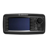
3.2.7.1 Pressure Sensing Overview
The signal runs from the pressure sensor travels as digital information on the CAN Bus to the central
processing unit.
Note that the load displayed on the LMI is not a direct measurement when using pressure transducers;
rather, it is a calculated value. Ensure that the hydraulic system is functioning as intended and that
sensor values, mainly length and angle, are functioning correctly prior to troubleshooting the pressure
transducers.
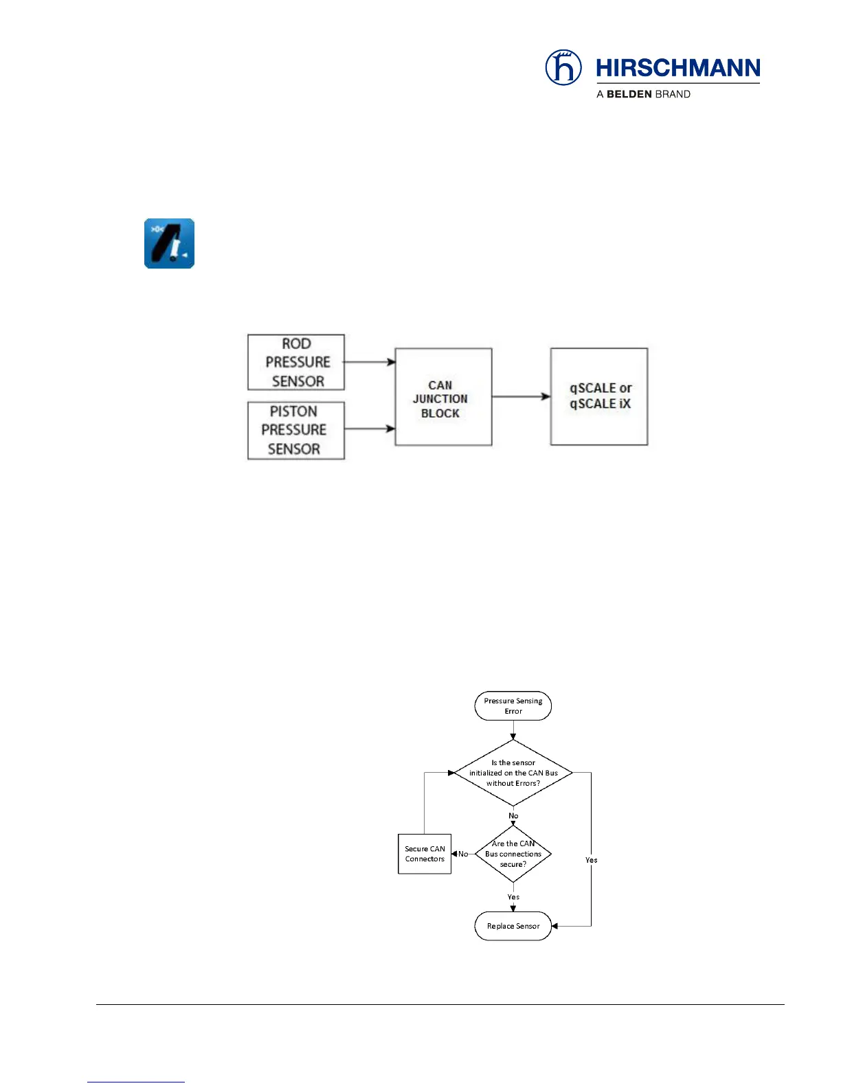
3.2.7.2 Pressure Sensing Error – Flow Chart
Use the following flow chart to troubleshoot errors with pressure sensing.