Troubleshooting
© 2016 Hirschmann Automation and Control GmbH · Mobile Machine Control Solutions · www.beldensolutions.com 35/161
qSCALE i2 Cranes (Tool Version 3.0.34) Service Manual / Issue B / 11-2017 / ac.
3.2.5 Boom Angle Sensing
The system measures the angle of the main boom of the machine with an angle sensor. The angle
sensor is either contained within the cable reel or mounted directly to the main boom.
3.2.5.1 Boom Angle Sensing Overview
The WGC angle sensor is based on liquid capacitive inclinometer technology. As the angle changes so
will the fluid, and with it the capacitance changes.
The WGX angle sensor is based on Micro-Electro-Mechanical Systems (MEMS) inclinometer. The
angle is measured with relative change in electrical capacitance in the MEMS cell.
Start by verifying the actual angle to display the angle at several positions. The CAN Bus is digital and
as such will either transmit the signal correctly or not at all. The raw value of the sensor can be moni-
tored and should be checked against a digital level outside of the system mounted on the boom. If the
raw value varies from the actual value, replace the angle sensor. Refer to sensor documentation for
expected accuracy values.
The voltage supplied to either sensor should ideally be between 11.0 and 26.0V. If the angle sensor is
mounted directly to the boom, the CAN Bus cable will supply the sensor with power. If the angle sensor
is located within a cable reel, it can be connected to either a LWG board or a CAN Junction Board. This
board will supply the sensor with power.
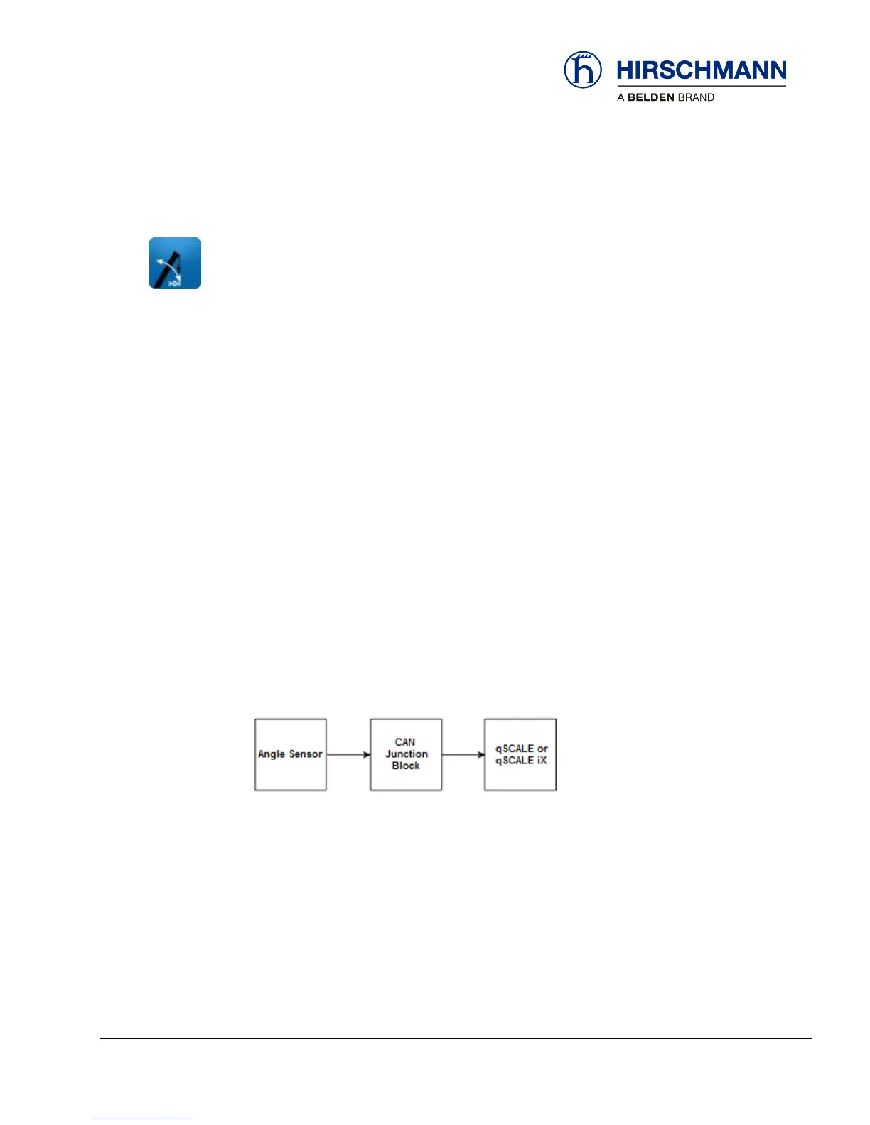
The signal runs from the angle sensor to the CAN junction block. From there, it travels as digital infor-
mation on the CAN Bus to the central processing unit.
Unplug the CAN cable from the angle sensor and measure the voltage between pins 3 (GND) and 2 (+).
If the voltage is outside of the acceptable range, power to the CAN line may be the issue. Check the
entire CAN Bus system to ensure proper wiring and connections.