Troubleshooting
© 2016 Hirschmann Automation and Control GmbH · Mobile Machine Control Solutions · www.beldensolutions.com 39/161
qSCALE i2 Cranes (Tool Version 3.0.34) Service Manual / Issue B / 11-2017 / ac.
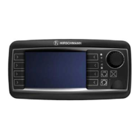
3.2.6.2 Rotary Encoder Troubleshooting
The rotary encoder is driven by a belt drive from the drum shaft, and thus does not contain a gear set
within the cable reel housing. The sensor outputs a CAN signal directly and plugs into a CAN Bus Junc-
tion Board. The ideal voltage supplied to the rotary encoder should be between 11.0 and 26.0V.
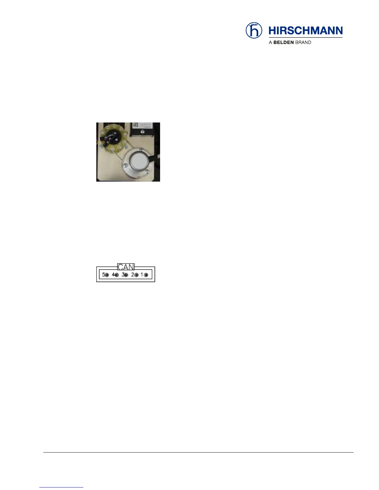
Measure the voltage between pins 3 (GND) and 2 (+) while the rotary encoder is still connected to the
CAN Bus Junction Board. If the voltage is not within the acceptable range, unplug the sensor and re-
measure. If unplugging the sensor resolved the voltage issue, replace the sensor. If the voltage is still
outside of the acceptable range, unplug the power source to the CAN Bus Junction Board and re-
measure. If unplugging the board resolved the voltage issue, replace the board. If the voltage is still
outside of the acceptable range, power to the CAN line may be the issue. Check the entire CAN Bus
system to ensure proper wiring and connections.
The CAN Bus Junction Board is a passive device that acts as a junction for CAN sensors.