General Information
1-27
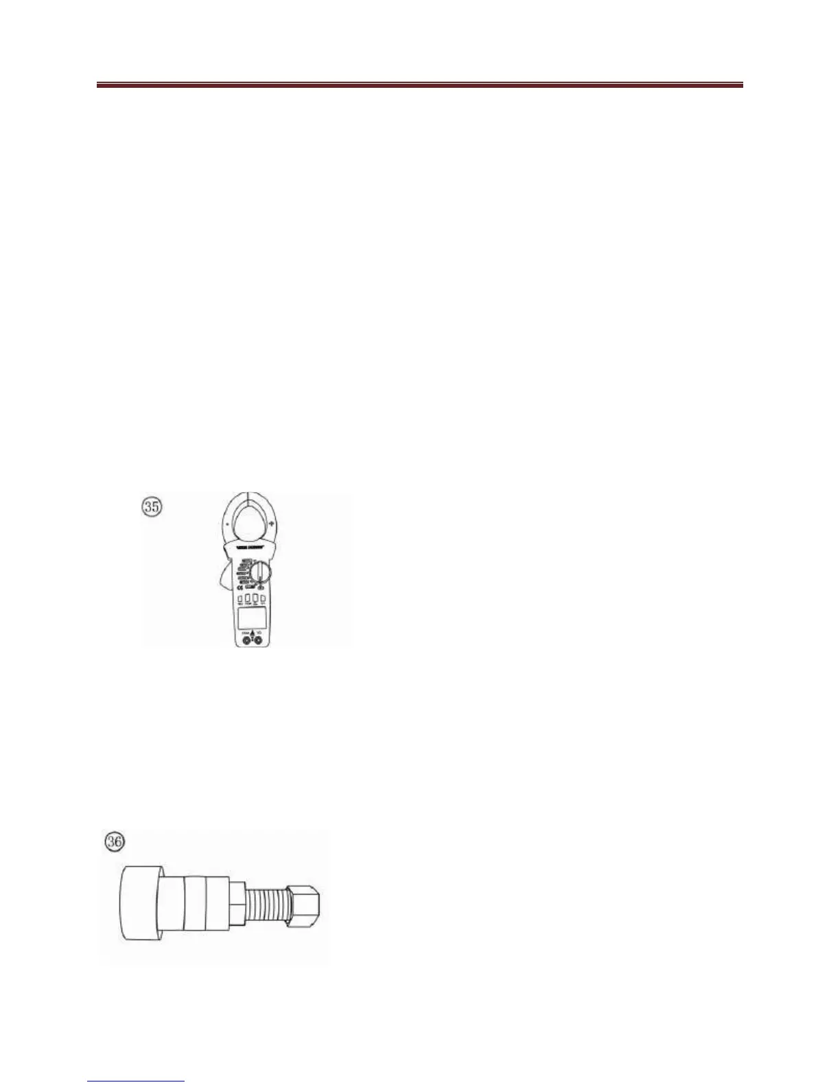
Clip-on ammeter
1. Clip-on ammeter (Figure 35) is
the basic tool for electrical
system diagnosis which is used
to measure the current of
charging system and other
electrical components that work
with current.
2. Clip-on ammeter can measure
direct current and alternating
current. Please ensure that the
battery in the tool is
sufficient to work the tool.
3. When you measure the current,
the caliper must clamp around
the positive pole of the power. If
clamped around the negative
pole mistakenly, a wrong result
will appear.
Magneto puller
Magneto drawing (figure 36) is special
tool to dismantle magneto rotor. First put
the mandril into the inside of the shaft
hole ,Turn the magneto rotor
accordingly, screw magneto drawing
and push-out the magneto rotor.
Electrical System
Fundamentals
A thorough study of the many types of
electrical systems used in today’s UTV’s
is beyond the scope of this manual.
However, a basic understanding of
electrical basics is necessary to perform
simple diagnostic tests. Refer to
Electrical Testing in Chapter Two for
typical test procedures and equipment.
Refer to Chapter Ten for specific system
test procedures.
Voltage
Voltage is the electrical potential or
pressure in an electrical circuit and is
expressed in volts. The more pressure
(voltage) in a circuit the more work can
be performed.
Direct current (DC) voltage means the
electricity flows in one direction. All
circuits powered by a battery are DC
circuits.
Alternating current (AC) means the
electricity flows in one direction
momentarily and then switches to the
opposite direction. Alternator output is
an example of AC voltage. This voltage
must be changed or rectified to direct
current to operate in a battery powered
system.
Resistance
Resistance is the opposition to the flow
of electricity within a circuit or
component and is measured in ohms.
Resistance causes a reduction in
available current and voltage.
Resistance is measured in an inactive
circuit with an ohmmeter. The ohmmeter
sends a small amount of current into the
 Loading...