4 Remove the corner pocket covers.
The corner pocket covers can be removed pulling Ⓐ part
toward the arrow direction in the gure below.
5 Check to ensure that the distance between the indoor unit
undersurface and the false ceiling undersurface is 16
+3
0
mm as shown in the gure below.
3
False ceiling
Indoor unit
6 Fix the screw “A” to the mounting seat of the unit leaving the
screw thread approx. 33mm.
? NOTE
Adjustthemark"PIPESIDE"oftheairpanelandthepipingconnection
side of the unit when mounting the air panel. If not, it may cause air
leakage.
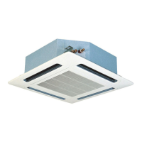
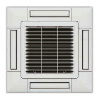
7 Temporarily x the air panel as following procedure. Hang
the air panel through the panel hole to the xing screw of “A”
(2 portions).
Fix the panel to the xing screw “A” by rotating it.
Fix the air panel by the four xing screws “A” and “B” (each
2 portions) securely as shown in the gure.
Do not use the impact driver or big torque tools using panel
mounting work.
33
A
B
A
B
Refrigerant pipe
Electrical box
Indoor unit
Indication
"PIPE SIDE"
Fixing plate
(Indoor unit)
Air panel
Mounting sheet
Long screw (Q'ty: 4pcs.)
8 Tighten the long screws until touching the stopper to the
xing plate.
When tightening the long screws to prevent air leakage
and to be no gap between the false ceiling surface and
the indoor unit, the inner circumference of the air panel
(the position to attach the air inlet grille) may be slightly
deformed.
However, it is not abnormality.
Corner of air panel
Enlarged view
Bottom side of
indoor unit
Fixing screw for air panel
False ceiling
? NOTE
The standard installation dimension between the indoor unit under
surfaceand the false ceiling surface is 16
+3
0
mm. If theposition and
thelevelnessoftheindoorunitarenotcorrect,theairpanelcannotbe
installedcorrectly.
AIR PANEL P-AP56NAM
PMML0570 rev.0 - 01/2021
5
EN
 Loading...


