20 GWF-7075 Addressable Fire Alarm Control Panel Manual — P/N LS10147-002GF-E:E 06/11/2019
Control Panel Installation Battery Power
4.3 Battery Power
Before you connect the batteries to the fire alarm control panel, make certain that the interconnect cable between the batteries is not con-
nected and be sure the following conditions exist before you connect the batteries.
• The batteries must be sealed lead acid type.
• Do not connect the battery jumper cable until the system is completely installed.
• Observe polarity when connecting the batteries
WARNING: RISK OF PERSONAL INJURY:
The Battery contains sulfuric acid which can cause severe burns to the skin, eyes and can destroy fabrics. If you make contact with sulfuric
acid, immediately flush your skin or eyes with water for 15 minutes and seek immediate medical attention.
The control panel battery charge capacity range is 7.0 A/H to 35 A/H.
• The main control cabinet can house batteries up to 7 A/H.
• The BB-17F holds up to two 18 Amp Hour Batteries.
Refer to Section 4.3.1 for details. Use 12V batteries of the same A/H rating. To determine the correct A/H rating as per your current load
calculation, refer to Section 3.7).
• Maximum battery charging current 3.1 Amps.
• Wire batteries in series to produce a 24-volt equivalent. Do not parallel batteries to increase the AH rating.
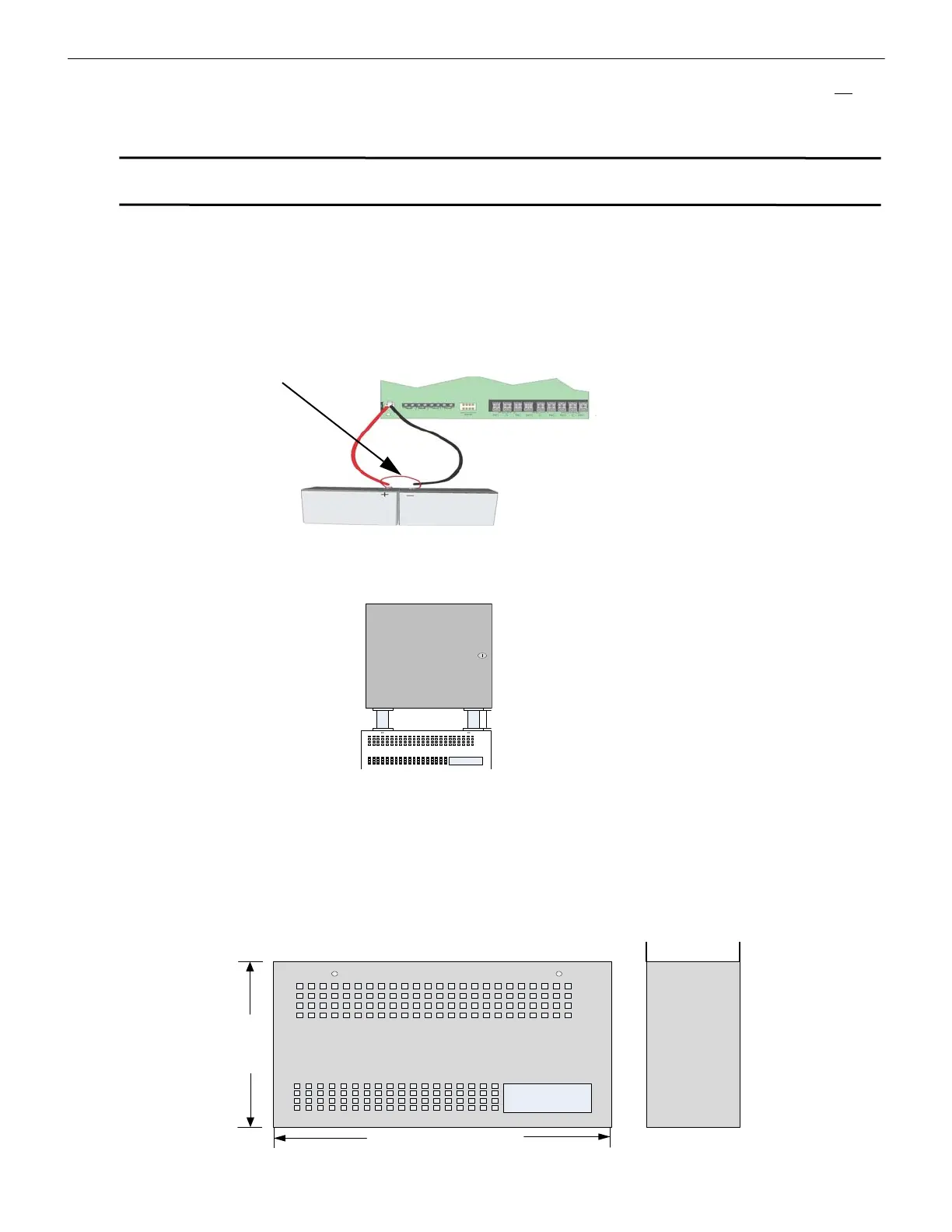
The following steps and diagram explain how to connect the batteries.
1. Connect the black wire from the control panel negative (–) battery terminal to the negative (–) side of Battery #2.
2. Connect the jumper wire provided (P/N 140694) from the positive (+) side of Battery #2 to the (–) negative side of Battery #1.
3. Connect the red wire from the control panel positive (+) terminal to the positive (+) side of Battery #1.
Figure 4.4 Battery Connection
4.3.1 .Battery Accessory Cabinet
The BB-17F Battery Box may be used to house up to two 17 A/H batteries. It mounts directly below the FACP cabinet. Knock-outs are
provided on the top surface of the battery box.
Figure 4.5 BB-17F Connection to FACP
4.3.2 BB-17F Cabinet Installation
To install the BB-17F cabinet, do the following:
1. Remove the knock-outs in the bottom of the FACP cabinet and the top of the BB-17F cabinet.
2. Align the knock-outs in the FACP and BB-17F (see Figure 4.5). Anchor the BB-17F cabinet to the wall using 1/4” diameter holes in
back of the cabinet.
3. Run conduit between the BB-17F cabinet and the FACP cabinet.
Make sure there is at least 6” (15.24 cm) of clearance between the BB-17F and the FACP (see illustration at left).
4. Run the battery cable through the conduit from the FACP into the battery box. Connect the cable to the batteries.
5. To secure the BB-17F cover to the cabinet, use supplied self-threading screws.
Figure 4.6 BB-17F Cabinet Dimensions
Red
Black
BatteryJumper
(P/N 140694)
Shipped with Panel
12V Battery
12V Battery
6 INCH (15.24 cm)
BB-17F Battery
BB-17F BATTERY BOX
Battery Box = 14.5”
(37.38 cm)
Battery Box = 8.5”
(21.59 cm)
Depth = 4.75”
(12.07 cm)

 Loading...


