22 GWF-7075 Addressable Fire Alarm Control Panel Manual — P/N LS10147-002GF-E:E 06/11/2019
Control Panel Installation RA-1000 Remote Annunciator Installation
4.4.2 Wiring Configurations
Figure 4.7 illustrates Class B configuration.
Figure 4.7 SBUS Class B Wiring
4.4.3 Procedure to Power SBUS Devices from an Auxiliary Power Supply
Figure 4.8 illustrates how to power SBUS devices from an Auxiliary Power Supply such as, the GFPS-6 or GFPS-9, when the maximum
number of SBUS devices exceeds the SBUS power requirements.
Figure 4.8 Powering SBUS Devices From GFPS-6 or GFPS-9
4.5 RA-1000 Remote Annunciator Installation
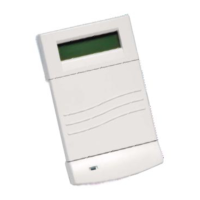
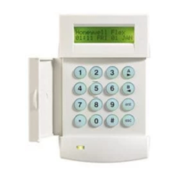
The optional Model RA-1000 Remote Annunciator, is shown in Figure 4.9. Up to 8 annunciators can be added to the GWF-7075 system.
Figure 4.9 Model RA-1000 Remote Annunciator, Front View
RA-1000 installation involves the following steps:
1. Make sure power is off at the panel.
2. Mount the RA-1000 in the desired location (see Section 4.5.1).
3. Connect the RA-1000 to the panel (see Section 4).
4. Use the dipswitches on the back of the RA-1000 to assign an ID# to the RA-1000 (see Section 4.8.1).
5. The new RA-1000 module must be added to the system through programming. JumpStart will add the module automatically (see
Section 6.1). You can also add it manually (see Section 7.2.2). Select a name, if desired (see , "Naming Modules").
Power supply
SBUS device
FACP
supervised
power limited
NOTE: The earth ground jumper on the GFPS-6/GFPS-9 must be removed in this configuration.

 Loading...


