GWF-7075 Addressable Fire Alarm Control Panel Manual — P/N LS10147-002GF-E:E 06/11/2019 21
SBUS Wiring Control Panel Installation
4.4 SBUS Wiring
This section contains information on calculating SBUS wire distances and the types of wiring configurations (Class B).
4.4.1 Procedure to Calculate the Wiring Distance for SBUS Modules
To determine the type of wire and the maximum wiring distance that you can use with the fire alarm control panel SBUS accessory mod-
ules, refer to the following instructions.
1. To calculate the wire gauge that you must use to connect the SBUS modules to the fire alarm control panel, it is necessary to
calculate the total “worst case” current draw for all modules on a single 4-conductor bus.
2. To calculate the total “worst case” current draw, add the individual “worst case” currents for each module. The individual “worst
case” values are shown in the table below.
3. After you calculate the total “worst case” current draw, refer to Table 4.4 to obtain the maximum distance the modules can be
located on a single wire run fromthe fire alarm control panel.
The table ensures 6.0 volts of line drop maximum. In general, the wire length is limited by resistance, but for heavier wire gauges,
capacitance is the limiting factor.
These cases are marked in the chart with an asterisk (*). Maximum length can never be more than 6,000 feet, regardless of gauge
used. (The formula used to generate this chart is shown in the note below).
Note: T
he following formulas were used to generate the wire distance chart.
Wiring Distance Calculation Example:
For example, if your system is configured with the following SBUS modules:
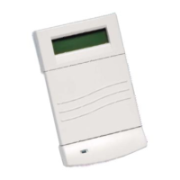
• 2 - Module RA-1000 LCD Annunciator
• 1 - GFPS-6S NAC Expander
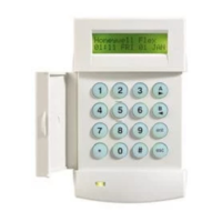
• 1 - 5824 Parallel/Serial Interface
You can calculate the total “worst case” current draw as follows:
NOTE: Total “worst case” current draw on a single SBUS cannot exceed 1 amp.
Model Number Worst Case Current Draw
RA-1000 LCD Annunciator .100 amps
5824 Serial/Parallel Printer Interface Module .040 amps
5880 LED I/O Module .250 amps
GFPS-6S NAC Expander .010 amps
CELL-MOD, CELL-CAB-GWF .145 amps
Table 4.1 Worst Case Current Draw
Wiring Distance: SBUS Modules to Panel
Total Worst Case Current
Draw (amps)
22 Gauge 18 Gauge 16 Gauge 14 Gauge
0.100 1852 ft. 4688 ft. * 6000 ft. * 6000 ft.
0.200 926 ft. 2344 ft. 3731 ft. 5906 ft.
0.300 617 ft. 1563 ft. 2488 ft. 3937 ft.
0.400 463 ft. 1172 ft. 1866 ft. 2953 ft.
0.500 370 ft. 938 ft. 1493 ft. 2362 ft.
0.600 309 ft. 781 ft. 1244 ft. 1969 ft.
0.700 265 ft. 670 ft. 1066 ft. 1687 ft.
0.800 231 ft. 586 ft. 933 ft. 1476 ft.
0.900 206 ft. 521 ft. 829 ft. 1312 ft.
1.000 (Max) 185 ft. 469 ft. 746 ft. 1181 ft.
Table 4.2 Wiring Distrance
Maximum Resistance (Ohms) = 6.0 Volts
Total Worst Case Current Draw (amps)
Maximum Wire Length (Feet) =
(6000 feet maximum)
Maximum Resistance (Ohms) * 500
Rpu
where: Rpu = Ohms per 1000 feet for various wire gauges (see table below)
Wire Gauge Ohms per 1000 feet (Rpu)
22 16.2
18 6.4
16 4.02
14 2.54
SBUS Modules Calculation Result
RA-1000 Current Draw = 2 x .100 amps = .200 amps
GFPS-6S Current Draw = 1 x .010 amps = .010 amps
5824 Current Draw = 1 x .040 amps = .040 amps
Total “Worst Case” Current Draw = .250 amps
Note: Using this value, and referring to the Wiring Distance table, it can be found that the available options are:
- 370 feet maximum using 22 Gauge wire
- 938 feet maximum using 18 Gauge wire
- 1493 feet maximum using 16 Gauge wire
- 2362 feet maximum using 14 Gauge wire
Table 4.3 Wiring Distance Calculation Example

 Loading...


