GWF-7075 Addressable Fire Alarm Control Panel Manual — P/N LS10147-002GF-E:E 06/11/2019 23
RA-1000 Remote Annunciator Installation Control Panel Installation
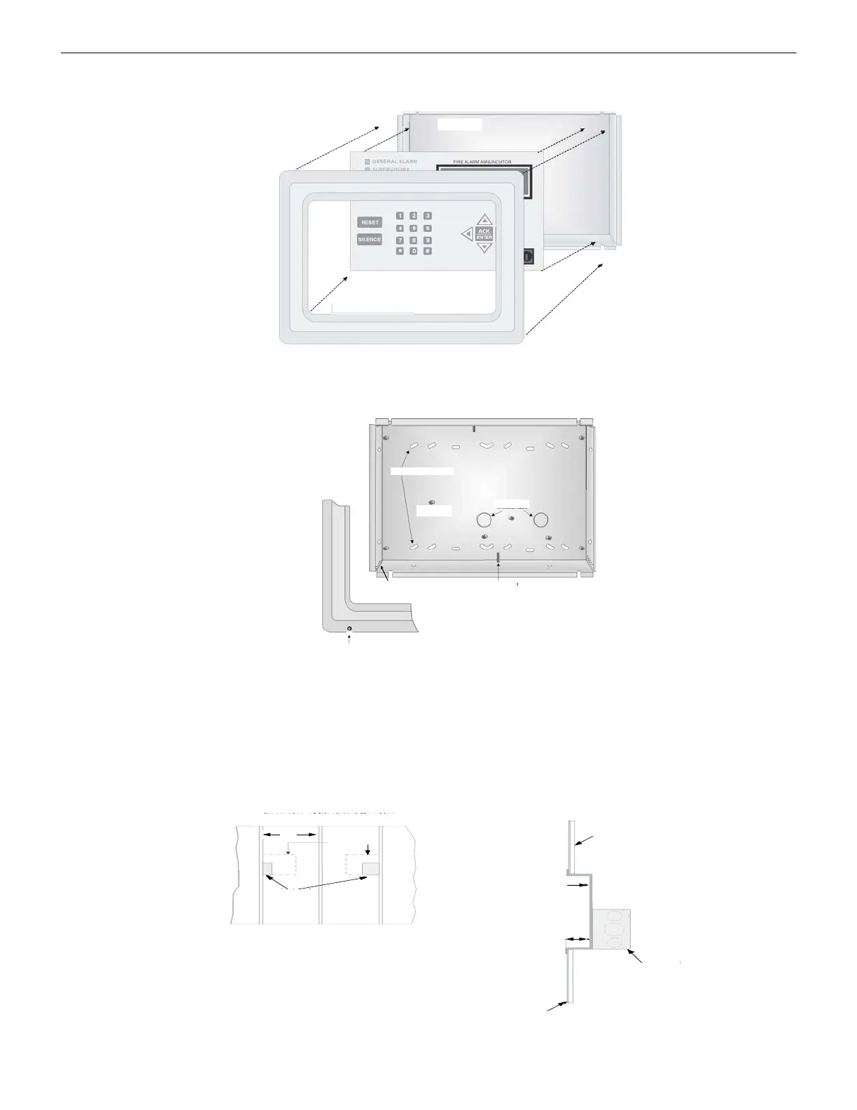
4.5.1 Mounting the RA-1000
This section of the manual describes mounting the remote annunciator. The annunciator can be flush- or surface-mounted. Figure 4.10
shows the parts of the annunciator. Instructions for disassembling and mounting appear on the following pages.
Figure 4.10 Annunciator Parts
The RA-1000 comes from the factory fully assembled. You must disassemble it for mounting. To disassemble the annunciator, use a 5/64
hex wrench to remove the set screws, located on the bottom of the annunciator bezel. (See Figure 4.11 for the location of the set screws).
.
Figure 4.11 Annunciator Back Box and Bezel Details
Flush Mounting
This section of the manual describes flush mounting. You can flush-mount with or without an electrical box.
Flush Mounting with an Electrical Box
The RA-1000 annunciator can be used with the following types of electrical boxes: 4S, single-gang, and double-gang.
If you use an electrical box, the box must be 1-3/8” set back from the face of the wall to accommodate the annunciator. You must use two
by fours (or larger) Studs to connect to an electrical box.
Figure 4.12 Placement of Electrical Box for Flush Mounting
Back Box
Electronic Assembly
(Front View)
Bezel (external ring)
Assembled Annunciator also includes
mounting wires and 4 screws.
Use knockouts
for surface
mounting
Standoff
throughout
Knockouts-
holes
Screws for placement
of mounting wires
(top & bottom)
When you disassemble
annunciator, to remove the
bezel, loosen set screws.
Use knockouts to insert
wires for flush mounting.
(located in all corners).
wall studs
Electrical Box Placement
Examples of use of Electrical Box
Annunciator
backbox outline
Electrical Box
Sheet rock
Annunciator backbox
Electrical Box
Sheet rock
Electrical boxes must
be installed 1 3/8” back
from the wall.
Electrical box
applications require
a minimum 2x4 construction.

 Loading...


