GWF-7075 Addressable Fire Alarm Control Panel Manual — P/N LS10147-002GF-E:E 06/11/2019 53
Point Programming
SWITCH
WATERFLOW Latching
Non Latching
Use this switch type for monitoring water flow in a sprinkler system. Switch
closure will cause a sprinkler alarm. Water Flow switches can be programmed
as latching or non-latching.
You can program a delay of up to 90 seconds to be used with a Water Flow
Switch. The delay allows for normal, brief changes in a sprinkler system water
pressure. The Water Flow alarm will not activate unless the switch is active for
the programmed delay time.
Note: Waterflow delay of the FACP and the waterflow device shall not ex-
ceed 90 seconds.
If a delay is used, the system begins counting down when the switch closes. If
the switch opens (restores) before the timer expires, a Water Flow alarm is not
generated. If the Water Flow Switch remains closed after the timer expires, a
Water Flow alarm will be generated.
SUPERVSY Latching
Non Latching
Use this switch type for tamper monitoring of sprinklers and other fire
protection devices. If a contact closes, a sprinkler supervisory event will be
generated. Supervisory switches can be latching or non-latching.
FIRE DRILL System-level, non latching switch. This switch is an alternative way of causing
a fire drill. It has the same operation as the fire drill option available from the
annunciator. When the switch is activated, a fire drill begins; when the switch is
de-activated, a fire drill ends.
SILENCE System-level switch provides an alternate way to silence the system; same
effect as pressing the Silence key.
RESET System-level switch provides an alternate way to reset the system; same effect
as pressing the Reset key.
SWITCH
(cont.)
PAS_ACK Positive acknowledge switch. This switch must be used in zones programmed
as Positive Alarm Sequence (see Table 7.2).
If an acknowledge switch closes when an alarm or trouble condition is not
already in progress, a trouble will occur.
You must use a UL listed normally open, momentary switch type. The switch
must be rated at 5V, 100 mA (minimum) and be used with an EOL resistor for
supervision.
ZN_AUX1 Latching Use these switch types if you want to monitor special zone-level conditions.
Non Latching
ZN_AUX2 Latching
Non Latching
SYS_AUX1 Latching Use these switch types if you want to monitor special system-wide conditions.
Non Latching
SYS_AUX2 Latching
Non Latching
DETECT SW Used to monitor conventional 4-wire detectors, a contact closure will generate
a detector alarm event.
TAMPER Latching Performs identically to a supervisory switch, but will be indicated as a tamper
switch on the LCD annunciator.Non Latching
MAN REL Manual release switch, typically a pull station.
ILOCK Interlock release switch input.
CO DETECT SW CO Detector Switch
CO SUPERVISORY
DETECT SW
CO Supervisory Detector Switch
STATUS PT Status Point Switch
NOTIF
OUTPUT PT Select Group Output Point, a general use notification type. Use for driving standard
notification appliances.
AUX CONST Use constant power for applications that require a constant auxiliary power
source. Power is always present at Constant circuits.
AUX RESET Use for auxiliary power, resettable applications. See Section , “Resettable
Power” to learn how this option operates.
AUX DOOR Use for auxiliary power, door holder applications. For example, if you were
using an auxiliary power supply for door holders, you would use this option.
See Section , “Door Holder Power” to learn how this option operates.
RELAY
OUTPUT PT Select Group Output Point, a general use relay type. Use for applications requiring a relay,
such as elevator recall.
AUX RESET Use for auxiliary power, resettable applications. See Section , “Resettable
Power” to learn how this option operates.
AUX DOOR Use for auxiliary power, door holder applications. For example, if you were
using an auxiliary power supply for door holders, you would use this option.
See Section “Door Holder Power” on page 41 for a description of how this
option operates.
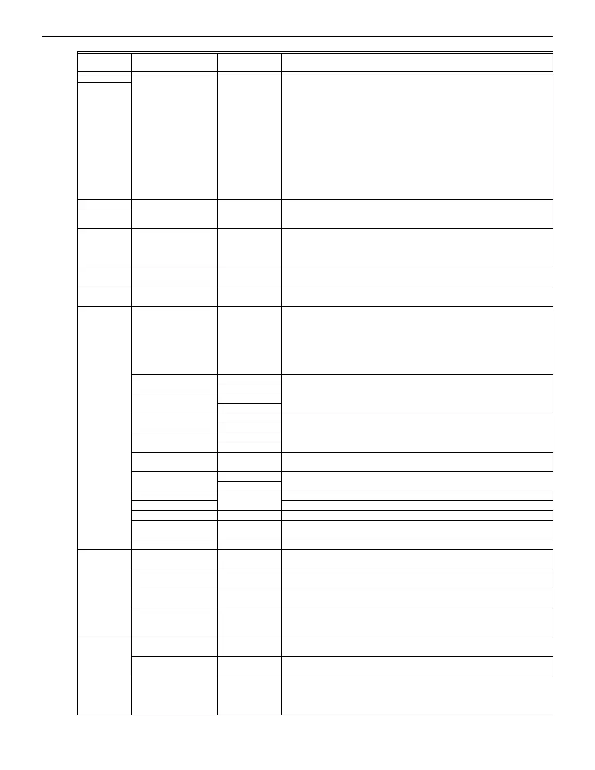
Type
Selection
Function Latching Option Comments
Table 7.4 : Point Programming for Internal SLC Modules (Continued)

 Loading...


