Commissioning
8
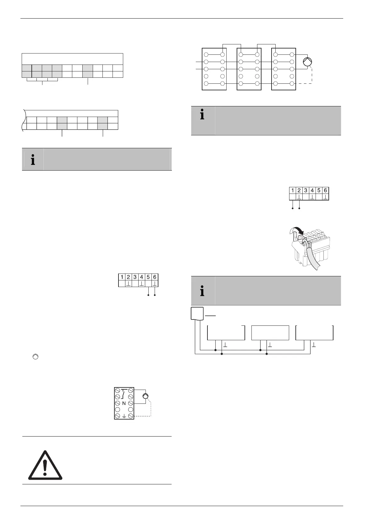
With controller MCR 40, the temperature and earth inputs
are located at the following terminals:
Earth input
78910456123
TW
Temperature input
Low-voltage side
MCR 40
With controller ZG 252 N, the temperature and earth inputs
are located at the following terminals:
456 10
TW
ZG 252 N
Earth input
789 1112
Temperature input
Depending on the design, the temperature selec-
tor and earth inputs are found on different termi-
nals of the controller MCR 200.
6.3.2. Implementing a boiler feedback via
a wireless connection (with
HC60NG/R6660D)
The relay is switched on and off depending on the valve
setting.
6.3.3. Implementing a boiler feedback with
an integrated relay 42 V AC, floating
contact (only HCE 80R/HCC 80R)
The relay is switched on and off depending on the valve
setting.
► Strip the connections 5.5 mm (see fold-out page, Fig. 5).
► Connect the boiler feedback
in accordance with the follow-
ing graphics (see the fold-out
page, Fig. 4 (9)).
TW
H/C
B+
6.4. Pump
6.4.1. Pump control
As soon as a zone is active, the pump is activated with a
time delay. The pump switches off as soon as all the valves
are closed.
The
LED (see fold-out page, Fig. 3 (6)) lights up green
when the pump is running.
6.4.2. Connecting a pump (230 V AC)
► Strip the connections 7 mm
(see fold-out page, Fig. 7).
► Connect the pump in accor-
dance with the following
graphics (see the fold-out
page, Fig. 4 (12)).
Pump
L
PE
WARNING
Damage to the underfloor heating
controller!
Short-circuit due to incorrect installa-
tion.
► Connect all the controllers to the
same phase.
Controller 1
L
N
PE
PE
N
Pump
Controller 2 Controller 3
6.4.3. Installing an external antenna
Up to three underfloor heating controllers can be
connected to an antenna. When selecting the
operating site ensure that the function of the
antenna is not impaired.
► Only install the external antenna outside metal housings
(e.g. control cabinets).
► Install the antenna at a suitable location near the under-
floor heating controller. Ensure that a radio connection to
the setpoint adjuster exists.
► Strip the connections 5.5 mm (see fold-out page, Fig. 5).
► Connect the antenna in accor-
dance with the following graphics
(see the fold-out page, Fig. 4 (9)).
Shield to 2
Second conductor to 1
B+ H/C
TW
► Close the terminals.
If several underfloor heating controllers are oper-
ated simultaneously, an antenna (internal or
external) may only be connected to one control-
ler.
Regler 1 Regler 2 Regler 3
B+ B+ B+
6.4.4. Closing the housing of the under-
floor heating controller
► Place the housing cover back on (see fold-out page).
► Snap the left and right snap lock back into place.
► Tighten the screws on the top.
7. Commissioning
During commissioning, setpoint adjusters – and the time
programs of the radio setpoint adjuster CM67z if applicable
– are assigned to the temperature zones of the underfloor
heating controller. A room name is defined for each tem-
perature zone at the Hometronic Manager.
7.1.1. Commissioning the underfloor heat-
ing controller
► Switch on the operating voltage.
The mains voltage LED (POWER) lights up.
ntenna
Controller 1
Controller 2
Controller 3

 Loading...