Displaying faults
12
10. Displaying faults
If the LED lights up, a fault exists in at least one tempera-
ture zone.
The colours of the zone LEDs 1...8 provide information on
the type of fault in the respective temperature zone:
Off No fault
Red
flashing
No connection to the setpoint adjuster, room
temperature sensor
Yellow
flashing
No connection to the setpoint adjuster and
Hometronic Manager HCM 200D or central
operating device CM67z
Green
flashing
No connection to the Hometronic Manager
HCM 200D or central operating device CM67z
The fault display extinguishes as soon as the fault has been
eliminated.
11. Completing commission-
ing
► Close the housing (see "Closing the housing of the under-
floor heating controller", Page 8).
► Hand over the completed zoning plan and the installation
instructions to the customer.
11.1. Note to installer
After the underfloor heating controller has been commis-
sioned, inform your customer about the heating control
system.
► Explain the function and operation of all the components to
the customer.
► Point out particular features to the customer and ensure
that they are aware of the possibility of expanding their
system.
11.2. Resetting underfloor heating con-
troller to state of delivery
All current assignments are lost if the underfloor
heating controller is reset to the state of delivery.
The underfloor heating controller retains its con-
figuration after a power failure.
► Keep the
Mode
and buttons at the underfloor heating
controller pressed simultaneously for at least 10 seconds.
After 4 seconds the controller changes over to
test mode Continue to keep the button pressed
until the LED flashes yellow.
The LED lights up yellow (flashes rapidly).
The underfloor heating controller is reset to the state of
delivery.
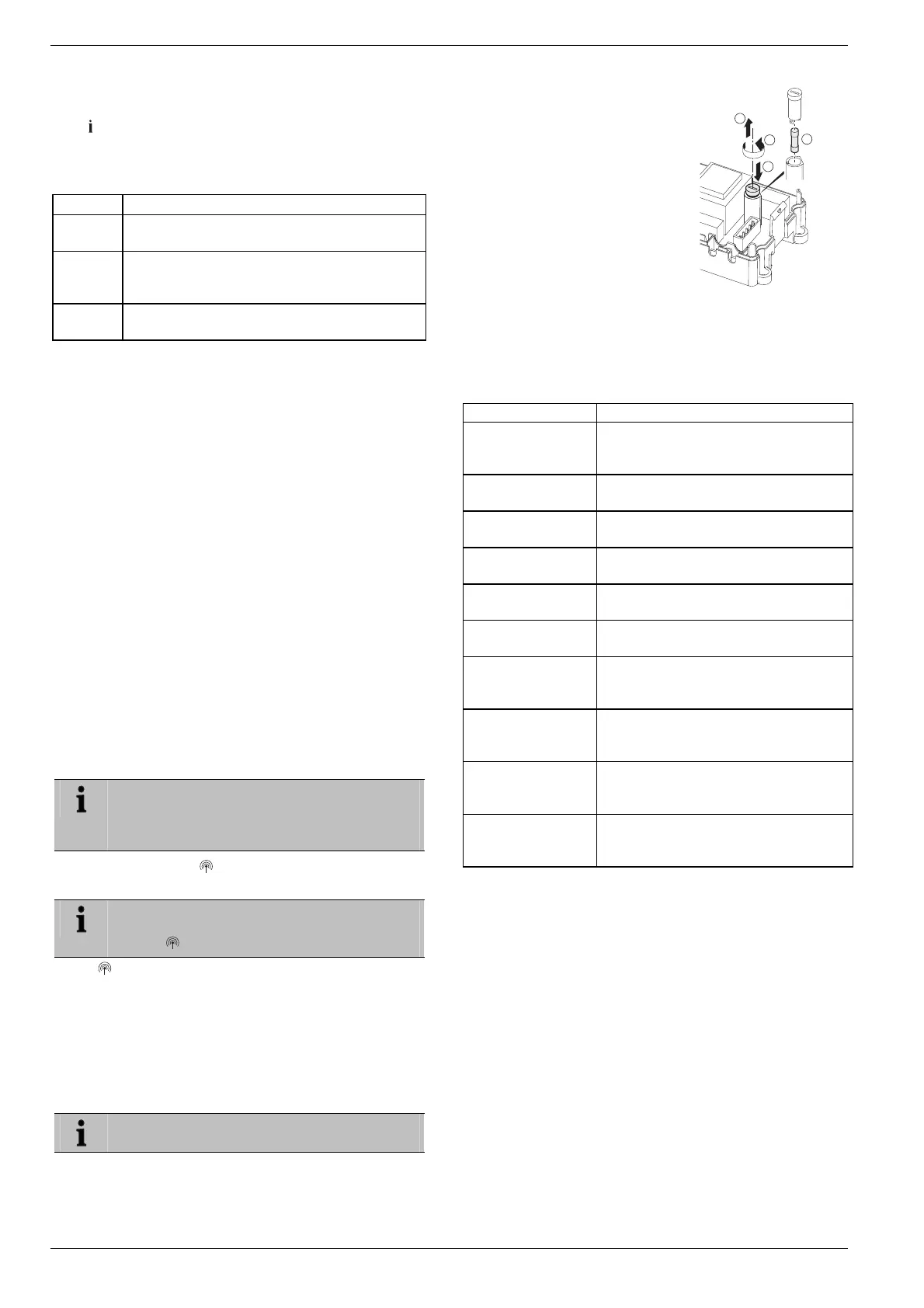
12. Changing the fuse
► Deenergize the device.
► Open the housing (see "Opening the housing", Page 6).
Only use ceramic fuses of the type 230 V AC;
2.5 A; fast; 5 x 20 mm.
► Remove the holder with the fuse
(Steps 1 to 3).
► Replace the fuse (4) by a new
one.
► Insert the holder again:
Inserting (1)
Turn to the right.
3
1
2
4
► Close the housing (see "Closing the housing of the under-
floor heating controller", Page 8).
13. Appendix
13.1. Glossary
Term Explanation
Boiler feedback
The control of the heat generator is
dependent on the amount of heat re-
quired.
Heating circuit
Totality of all the control and regulating
devices of a temperature zone.
Hometronic
Home automation system from Honey-
well.
Hometronic Man-
ager
Central operating device of the Homet-
ronic System.
Integrated Pump
Relay
Controls a pump that is connected to the
underfloor heating controller.
Room setpoint
temperature
Room temperature that is to be reached.
Room temperature
sensor
Detects the room temperature and
transfers it to the underfloor heating
controller.
Setpoint adjuster
Detects the actual temperature, changes
the setpoint temperature. Installed in a
user-friendly location in each zone.
Thermal actuator
Opens and closes a heating circuit. Is
controlled by the underfloor heating
controller.
Time program
Pre-defined setpoints and switching
points adjustable at the Hometronic
Manager and at the CM67z.

 Loading...