Installation and configuration
6
5.1. Wall installation
Four 4.2 mm holes for installation are located on the under-
floor heating controller.
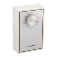
Take the 52 mm installation height of the under-
floor heating controller into account. If the under-
floor heating controller is installed at a severe
angle, the transformer must be on top to allow for
ventilation.
57
337
85
349.5
52.0
∅
4.2
Dimensions of underfloor heating controller in mm
► Mark, drill and insert plugs into fastening holes.
► Screw on the underfloor heating controller.
5.2. DIN rail installation
► Place the housing on the DIN
rail from below (1).
► Press the housing upwards
until it snaps into place (2).
5.3. Installing components
Install the components as described in the accompanying
installation instructions.
6. Installation and configura-
tion
DANGER
Danger to life through electric
shock!
Contacts that are open are live.
► Unplug the power plug before open-
ing the housing.
► Have all the work carried out by
authorised specialist personnel.
► All wiring must be in accordance with
IEE & Building Regulations.
WARNING
Damage to exposed components!
Destruction of the electronic compo-
nents through electrostatic discharges.
► Do not touch the components.
► Touch an earthed piece of metal to
discharge static electricity from your
body.
6.1. Opening the housing
► Open the housing as shown in Fig. 2 on the fold-out page.
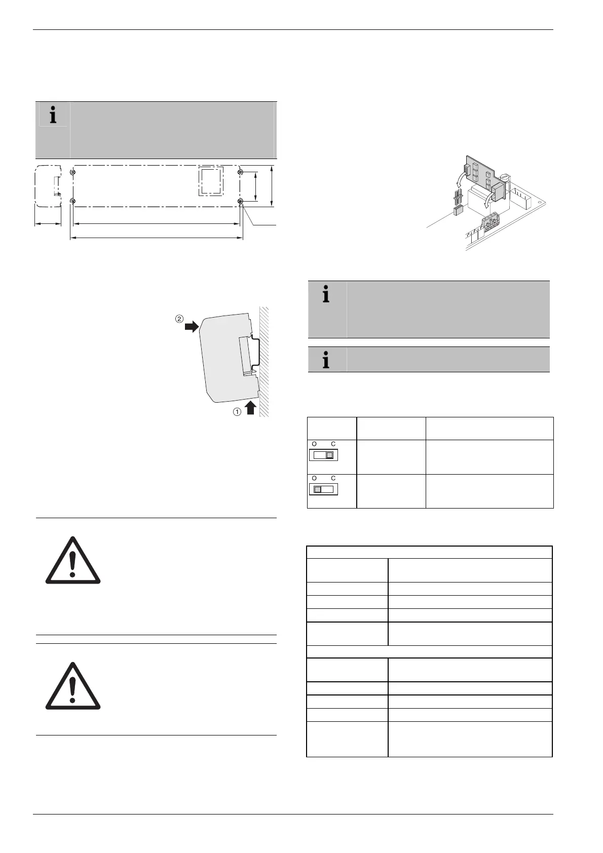
6.1.1. Plugging in the expansion module
(optional)
The expansion module HCS 80 expands the number of
possible temperature zones of the underfloor heating con-
troller from 5 through 8.
► Insert the expansion
module with the adapter
connector into the pro-
vided slot.
6.1.2. Setting the thermal actuator type
Only one thermal actuator type can be connected
per underfloor heating controller. If normally open
and normally closed actuators are to be oper-
ated, you require two underfloor heating control-
lers.
The thermal actuators are protected by a ceramic
fuse.
► Check the type of thermal actuator being used.
► Set the switches in accordance with the following table
(see the fold-out page, Fig. 4 (10)):
Switch
position
Thermal actua-
tor type
Property
Normally closed
Opens the heating circuit if
power is present at its control
input
Normally open
Opens the heating circuit if
power is not present at its
control input
6.2. Cabling connections
6.2.1. Permissible cable types and lengths
Thermal actuators
Outer cable diame-
ter
Min. 3.5 mm/Max. 5.3 mm
Cable length Max. 400 m
Cable cross-section Max. 1.0 mm²
Stripping length 4 mm
Terminal range of
the connectors
0.07–1.33 mm²; flexible wire
Power and pump connection 230 V AC
Outer cable diame-
ter
Min. 8.0 mm/Max. 11 mm
Cable length Max. 100 m
Cable cross-section Max. 1.5 mm²
Stripping length 7 mm
Terminal range of
the connectors
0.50–2.50 mm²; flexible/fixed connection
0.50–1.50 mm²; flexible, with wire end
ferrule

 Loading...