Appendix
13
13.2. Help with problems
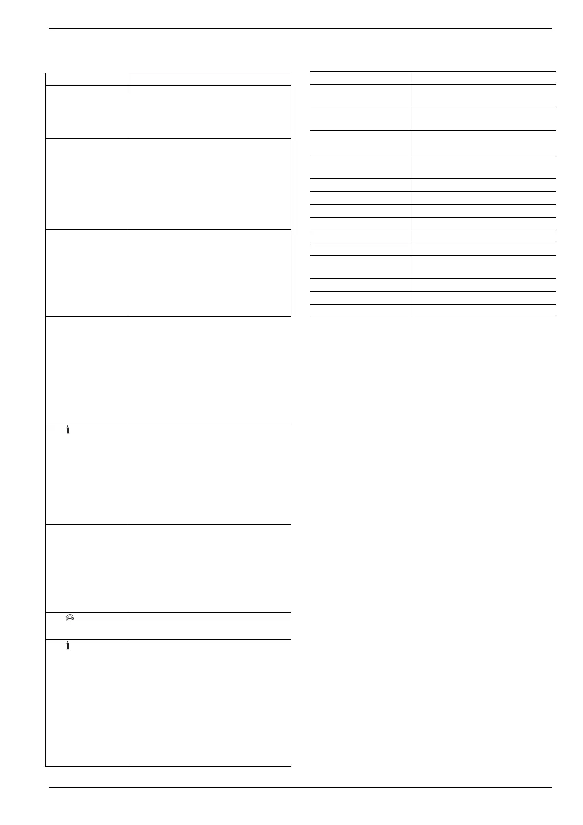
Problem Cause/Solution
Power LED does
not light up when
the power is
switched on.
Mains voltage not connected.
► Check voltage of electrical outlet.
► Check fuse at underfloor heating
controller.
LEDs 1...8 of the
zones do not illumi-
nate green continu-
ously during start-
up.
The room name is not assigned.
► Check whether or not the Hometronic
Manager is installed.
► Check whether or not a room name is
assigned to zone.
► Check the antenna connection.
► Reassign the zone, if applicable.
LEDs 1...8 of the
zones do not illumi-
nate red continu-
ously during start-
up.
The setpoint adjuster cannot be as-
signed.
► Check whether or not batteries in
setpoint adjuster are inserted prop-
erly.
► Check wireless connection.
► Check the antenna connection.
Rooms are not
heated/cooled.
► Check heating and inlet temperature.
► Check adaptation to thermal actuator
(see Page 6).
► Check fuse of underfloor heating
controller.
If fuse is defective:
► Check actuators for short circuit.
► Change the fuse.
The LED lights up
red after commis-
sioning.
There is a fault in one of the tempera-
ture zones (see Page 12).
► Check wireless connection.
► Check the antenna connection.
► Check whether or not zone is as-
signed correctly.
► Check the batteries of the allocated
devices.
Room controlled
incorrectly.
► Check whether or not adjustment dial
of setpoint adjuster is at position 0.
► Check whether or not the adjusting
ring can be turned between -12 and
+12 with the housing cover removed.
► Check whether or not a setpoint
adjuster is assigned to room.
The LED flashes
rapidly.
No device installed.
► Install the devices again.
The LED flashes.
No antenna connected or antenna
defective.
► Check whether or not an antenna is
connected.
If no antenna is connected:
► Connect an antenna.
If an antenna is connected:
► Check the antenna connection.
► If applicable, replace the antenna by
a new one.
13.3. Technical data
Input/Output voltage 230 V AC, 50 Hz
Power consumption
Max. 1750 VA with connected pump
(max. 6 A)
Pump relay
Switching contact 230 V AC, max.
6 A (not floating) ; cosϕ ≥ 0.7
Boiler feedback relay
42 V AC; 1 V < U ≅ 42 V;
1 mA < I ≅ 100 mA; cosϕ = 1
Thermal actuators
2.7 A max. for 1 sec; 200 mA;
cosϕ ≥ 0.95
Ambient temperature 0 to 50°C
Storage temperature -20 to +70°C
Humidity 5 to 93 % relative humidity
Frequency 868.3 MHz (transmitter/receiver)
Dimensions 350x82x52 mm (WxHxD)
Weight 1 kg
Fuse
Ceramic fuse 5x20 mm, 230 V AC;
2.5 A; fast
Material ABS
Degree of protection IP30
Fire class V0
13.4. Device and function definition in
accordance with EN 60730-1
• Purpose of the device is temperature controlling
• Device fulfils Protection class 1, EN60730-1,
EN60730-2-9
• Independently installable electronic control system with
fixed installation
• Type of action is Type 1.B (pump relay) and Type 1.C
(thermal actuator)
• Temperature for ball-thrust hardness test for housing
components 75 °C and for live parts such as, for exam-
ple, terminals 125 °C
• EMC emitted interference test at 230 V AC +10/-15 %,
1750 VA maximum
• Pollution severity is 2
• Rated voltage is 4000 V (corresponding to Overvoltage
category III)
• Software class is A

 Loading...