Creating a zoning plan
5
3.1. Differences between the individual
device types
HCE 80 HCE 80R HCC 80 HCC 80R
Antenna
External External Internal Internal
Pump
relay
230 V AC
internal
230 V AC
internal
230 V AC
internal
230 V AC
internal
Analog
output
Exists Does not
exist
Exists Does not
exist
Boiler
feedback
radio
External
with
HC60NG/
R6660D
External
with
HC60NG/
R6660D
External
with
HC60NG/
R6660D
External
with
HC60NG/
R6660D
Boiler
feedback
relay
Does not
exist
42 V AC/DC Does not
exist
42 V AC/DC
The pump relay 230 V AC is not floating.
3.2. Function overview
• 5 controllable temperature zones, extendable to 8
• Up to 3 thermal actuators can be connected per zone
• Normally open and normally closed thermal actuators
can be used
• Integrated pump relay
• Boiler feedback
– Analog (only HCE 80/HCC 80)
– Integrated relay with floating contact 42 V AC/DC
(only at HCE 80R/HCC 80R)
– Wireless via relay HC60NG/R6660D
• Underfloor heating controller can be switched between
heating and cooling
• 1 antenna can be used for 3 controllers
• Internal or external antenna can be used
• Rapid mounting by screwless terminals of the thermal
actuators
• Intelligent controlling via fuzzy logic
• Simple diagnosis of the wireless transmission
• Operating state display via LEDs
4. Creating a zoning plan
Within a building rooms (zones) can be controlled with dif-
ferent room setpoint temperatures. The thermal actuators of
the allocated zone (room) are controlled depending on the
room setpoint temperature.
A maximum of 5 temperature zones can be set
for each underfloor heating controller. This num-
ber can be increased to 8 by using the expansion
module HCS 80.
A maximum of 3 actuators can be connected in
each zone.
Temperature zones
(maximum)
Actuators
(maximum)
No. of underfloor
heating control-
lers
8 24 1
16 48 2
24 72 3
Tab. 1: Overview of temperature zones/ underfloor heating control-
lers
4.1. Specifying temperature zones
► Specify the number of zones and corresponding rooms.
► Allocate the corresponding room device, for example
HCW 82, CM67z, and the required thermal actuators to
each zone.
► Label the room devices and thermal drives for the respec-
tive zone (refer to the fold-out page Fig. 4, Z1...Z8).
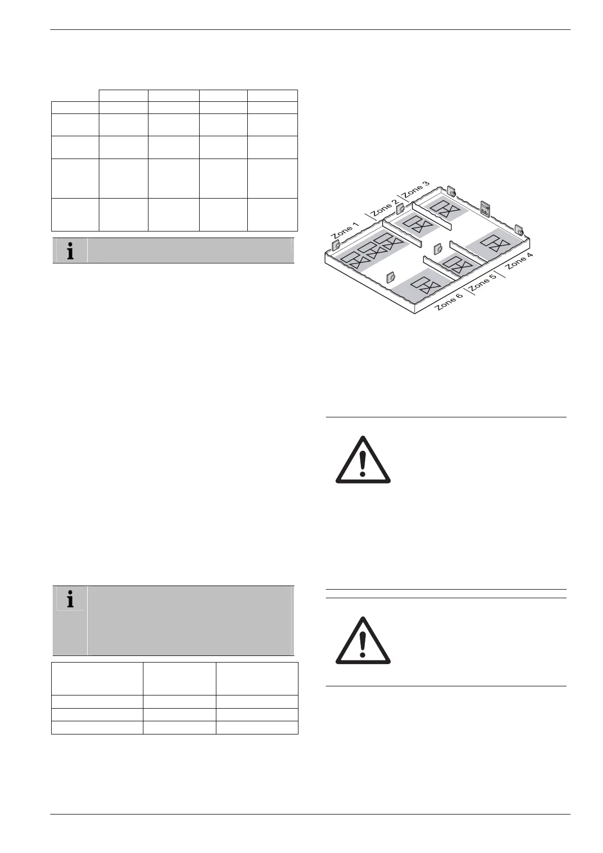
4.1.1. Example of zone divisions
living room
dining room
kitchen
hall
bedroom
bathroom
toilet
Explanation of this example:
• The living area is covered by six temperature zones. The
additional module HCS 80 is required for this parti-
tioning.
• The underfloor heating controller controls 8 actuators.
5. Installation
WARNING
Insufficient data transfer!
Interference of the radio receiver in the
device through metallic objects and
further radio devices.
► When selecting the operating site
ensure that the distance to radio de-
vices such as radio headphones,
cordless phones, etc. according to
the DECT standard amounts to at
least 1 m.
► Ensure that there is sufficient dis-
tance to metallic objects.
► Select another installation site if the
radio interference cannot be rectified.
WARNING
Damage to the underfloor heating
controller!
Short-circuiting through humidity and
moisture.
► Mount the device at a site that is
protected against humidity and mois-
ture.
The underfloor heating controller was designed for installa-
tion in a distributor box. If insufficient space is available,
select an area where the underfloor heating controller can
communicate with the setpoint adjusters by radio without
interference and that is protected from moisture and water.
The underfloor heating controller can be installed in one of 2
ways:
• Wall installation
• DIN rail installation

 Loading...