Appendix
15
13.7. Brief instructions
► Specify which heating circuits are to be controlled
by the underfloor heating controller.
See Section "Creating a zoning plan", Page 5.
► Mount the required components.
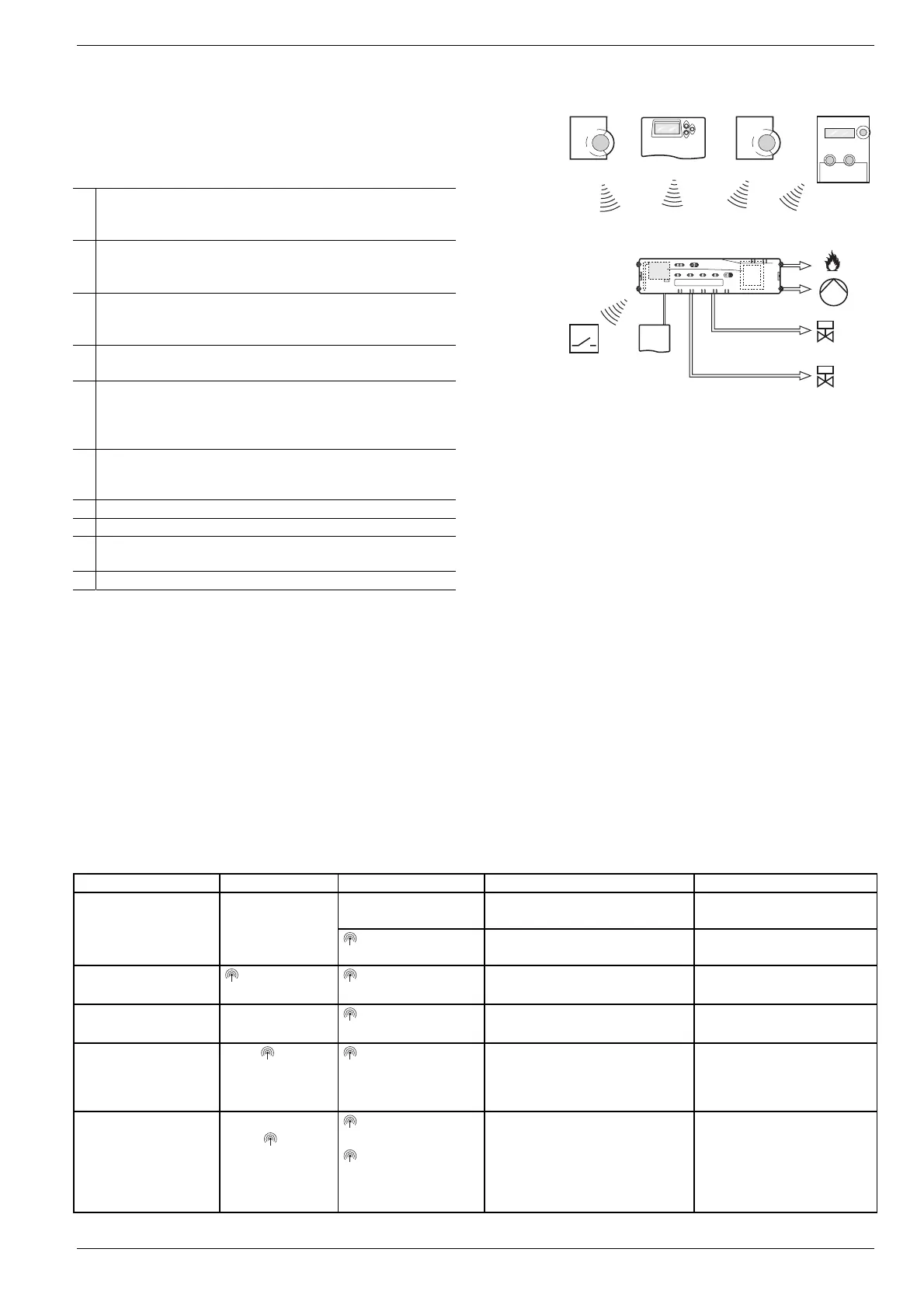
A Setpoint adjuster HCW 82
Controls the setpoint temperature for each temperature
zone via adjustment dial
B Central operating device CM67z
Controls the room temperature via programmable time
programs
C Room temperature sensor HCF 82
Transmits room temperature information to underfloor
heating controller
D Hometronic Manager HCM 200D
Central operating unit of the house-automation system
E underfloor heating controller
HCE 80/HCC 80/HCE 80R/HCC 80R
Controls actuators; communicates with setpoint adjusters
and room temperature sensors
F Boiler feedback,
Analog output (only HCE 80/HCC 80) or
Relay output (only HCE 80R/HCC 80R)
G Integrated pump relay
H Thermal actuators
I External antenna HCE 80/HCE 80R
Internal antenna HCC 80/HCC 80R
J Boiler feedback relay HC60NG/R6660D
See Section "Installation", Page 5.
► Set the underfloor heating controller to the corresponding
thermal actuator (normally open or normally closed), cable
the connections and interconnect the components.
See Section "Installation and configuration", Page 6.
► Assign the room temperature sensors, setpoint adjusters and
other control components to the temperature zones (teach-in).
If you use time programs:
► Assign room names at the Hometronic Manager, if applicable.
► Assign a time program of the CM67z to the temperature
zones, if applicable.
See Section "Commissioning", Page 8.
13.7.1. Navigation and function overview
Function Press button Status LED Zone LED Exit mode
Lights up green = Valve open
LED off = Valve closed
Normal mode -
LED flashes yellow
Allocate device
(e.g. HCW 82)
Teach-in
> 2 s
LED lights up
yellow
Flashing 4 min after last action
Delete allocated
devices
Mode > 4 sec in
teach-in mode
LED lights up
yellow
Zone LED extinguishes 4 min after last action
Device display
Keep pressed
for < 2s
LED flashes yellow
Red = Room actual value
Green = Time program
Yellow = Room actual value/time
program
• Automatically after 60 s
or
• Press other button
Cooling mode
Mode > 4 s
Press button
in order to acti-
vate/de-activate
cooling mode
LED green = Cool-
ing mode active
LED red = Cooling
mode inactive
Red = Cooling active and cool-
ing contact open
(Class 3 and 4)
Green = Cooling active and
cooling contact closed
(Class 3 and 4)
• Automatically after 60 s
or
• Press Mode button
(E)
(F)
(G)
(H)
(D)
(C)(A)
(B)
(I)
(I)
(J)

 Loading...