Installation and configuration
7
Antenna connection
Cable length Max. 30 m
Cable cross-section
JE-LiYCY 2x2x0.5 mm²;
JE-Y(St)Y ∅2x2x0.8 mm;
2x0.5 mm²
Stripping length 5.5 mm
Terminal range of
the connectors
0.07–1.54 mm²
Heating/cooling, boiler feedback
Cable length Max. 100 m
Cable cross-section
JE-LiYCY 2x2x0.5 mm²;
JE-Y(St)Y ∅2x2x0.8 mm;
2x0.5 mm²
Stripping length 5.5 mm
Terminal range of
the connectors
0.07–1.54 mm²
Tab. 2: Permissible cable types and lengths
6.2.2. Connecting power cable
DANGER
Danger to life through electric
shock!
Contacts that are open are live.
► Ensure that the cable is deenergized.
► Select a suitable cable in accordance with Table 2 for the
power supply.
► Strip the connections 7 mm (see fold-out page, Fig. 7).
► Connect the cable to the connector in
accordance with the graphics (see
fold-out page, Fig. 4 (12)).
► Plug the connector into Socket 12
(see the fold-out page, Fig. 4).
L
► Secure the cable with the cable clamp.
Installation Disassembling
6.2.3. Connecting the thermal actuators
WARNING
Damage to the underfloor heating
controller!
► Take the technical data into account
at thermal actuators: Total of 3 A
maximum current, 250 mA continu-
ous current per zone.
Each zone can control up to 3 actuators. 3 actuators can be
connected directly for zone 1, 2 for zone 2 and 1 each for
zones 3 through 5. One connection for the expansion mod-
ule is available for each of the zones 6 through 8.
If more than 11 thermal actuators are to be connected to the
underfloor heating controller, the cables of the actuator must
be wired in a distribution box.
► Lay the actuator cables to the distribution box.
► Connect the actuator wires.
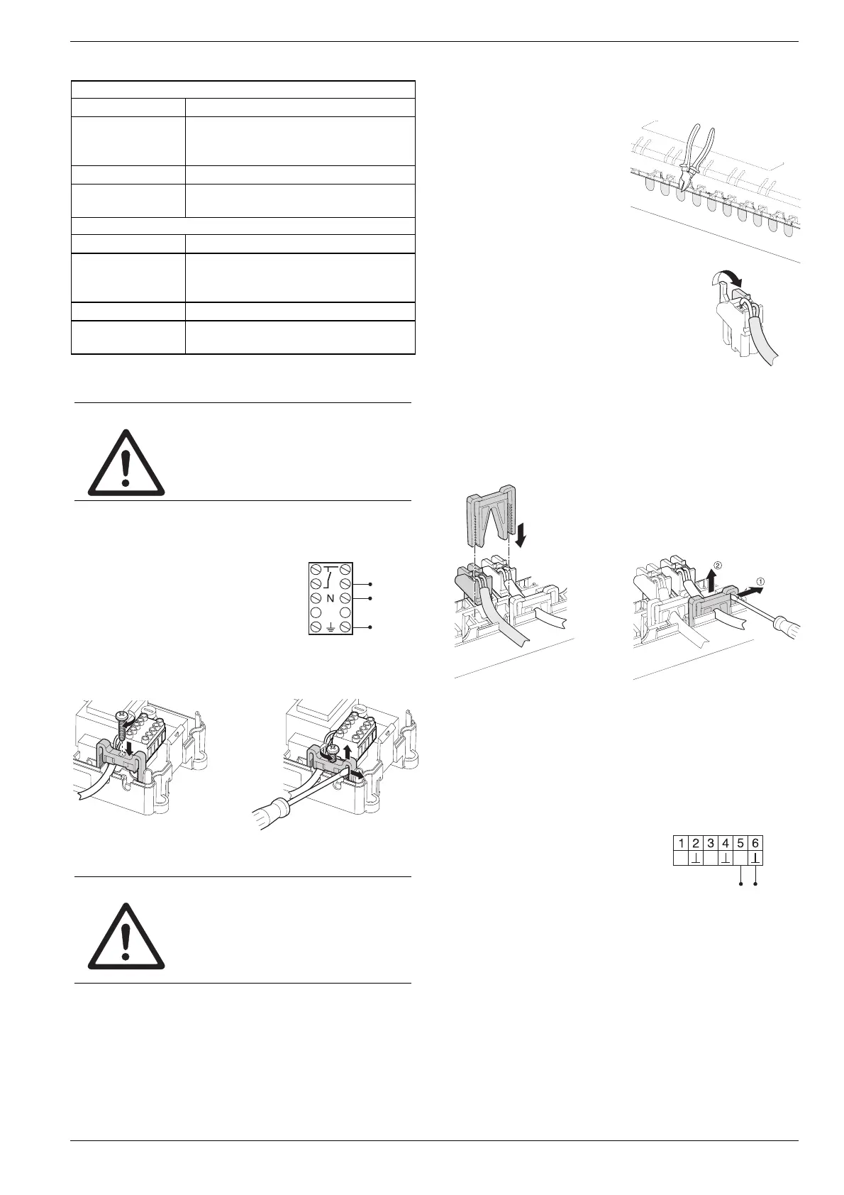
► Break out the openings for
the cables on the housing
using a diagonal cutter.
► Strip the connections 5.5 mm (see
fold-out page, Fig. 6).
► Insert the connecting cables of the
actuators into the cable openings of
the connectors.
► Close the terminators.
► Plug the connectors into the sockets of the corresponding
zones (see the fold-out page, Fig. 4 (Z1 -Z8)).
► Clamp the cables into the stress relief clamp.
► Secure the cable with the cable clamp.
Installation Disassembling
6.3. Boiler feedback
6.3.1. Connecting the boiler feedback via
an analog output (only HCE 80/
HCC 80) to external controllers
The analog output voltage changes depending on the valve
position.
► Strip the connections 5.5 mm (see fold-out page, Fig. 5).
► Connect the boiler feedback
in accordance with the fol-
lowing graphics (see the
fold-out page, Fig. 4 (9)).
TW
H/C
B+
Boiler feedback is possible with the controllers MCR 200,
MCR 40, ZG 252 N, Panther and Smile.
► Connect the controller inputs in accordance with the en-
closed instructions (earth input to Terminal 6, temperature
input to Terminal 5 of the underfloor heating controller).

 Loading...