46
Mounting and Connection Instructions IK3 Evaluation Unit BUS-2
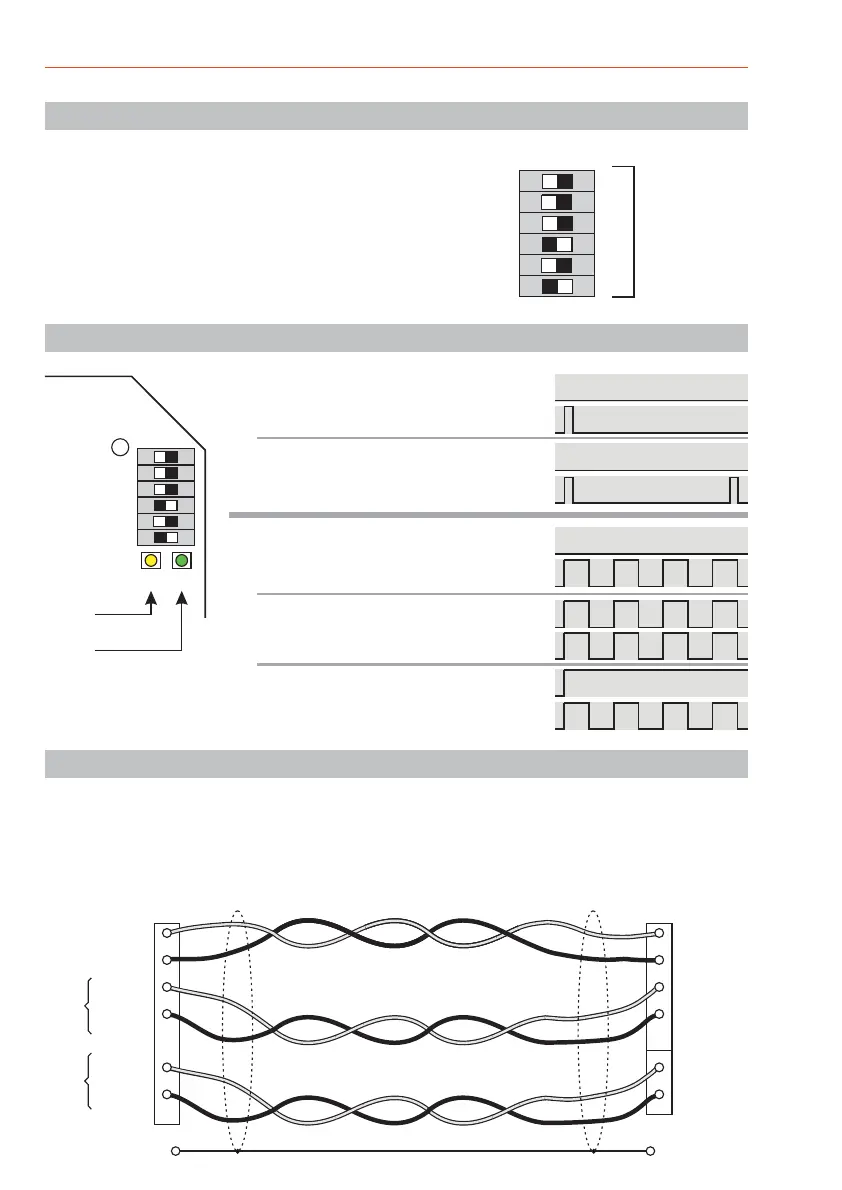
32
16
8
4
2
1
1234 5 6
ON
123456
ON
JP22
LD1 LD2
Address
switch
BUS-2
Yellow
Green
Off
Off
Flashes 1x
Always off
Flashes 50ms / 2s
LD1
LD2
LD1
LD2
LD1
LD2
LD1
LD2
LD1
LD2
Normal operation:
Boot loader active
- RAM is initialized when started
- When in operation, EU is
initialized by the central control
unit.
- Firmware downloaded
- Testing firmware after update
- Faulty firmware
5. Programming BUS-2 address
The DIP switches located in the IDENT-KEY evaluation
unit (address switch S1) are for setting the BUS-2 user
address. The individual codes can be found in the
programming protocol of the intrusion detection control
panel.
Indicated switch position = set!Address 5
Address switch S1
Address value
6. LED indicators
7. Installation guidelines
The BUS connection lead be a shielded cable stranded in pairs and the cores laid according to
the diagram below.
The corresponding line cross-sections can be found in the of the intrusion
detection control panel (Chapter on lines). The shield terminal should also be kept as short as
possible to avoid the risk of an unintentional short circuit.
must
Installation Manual
Data
0 V
+12 V DC
0 V
0 V
+12 V DC
Data
0 V
0 V
+12 V DC
0 V
+12 V DC
U_b
U_ext.
control panel EU ST1/ST2BUS-2
Shield Shield
 Loading...