Mounting and Connection Instructions IK3 Evaluation Unit BUS-2 49
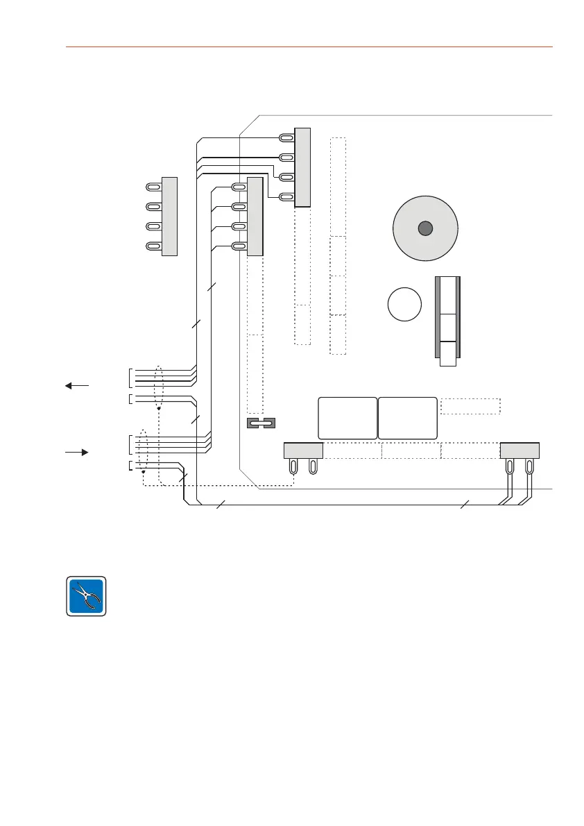
Note: BUS-2 connection technology does not require an end of line resistor.
The two pins of ST14 are , e.g. to connect U_ext. Therefore no
connection to the PCB exists.
soldering tags
BUS-2
U_ext.
BUS-2
U_ext.
DB1
ST23 ST11 ST12 ST13
ST18
ST5
ST4
ST19
ST21
ST2
ST1
ST3 ST20 ST10
ST9
ST14
Rel 1 Rel 2
+ 0V
U_ext.12 V DC
Cable shields
Cover contact
Buzzer
4
2x22x2
2
4
2
from control
panel
to next user
Shield
D
0 V
+
0 V
Data
0 V
+U_b 12V DC
0 V
ST1
BUS-2
ST2 is equivalent to ST1
Debridge the wire jumper DB1 if cable shield spikes also affect the operating voltage.
For detailed information on installation, grounding and shielding, please refer to the installation
manual of the corresponding intrusion detection control unit and the leaflet "
” (P03061-15-000-XX).
Electrical Installation
of hazard detection systems
9.2 control panelConnection of the
 Loading...