57
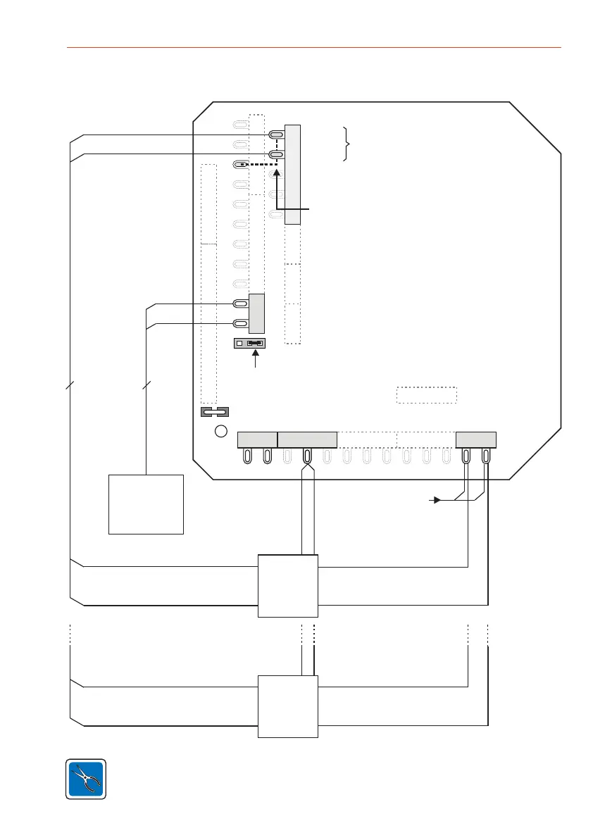
Mounting and Connection Instructions IK3 Evaluation Unit BUS-2
ST10
DB1
ST23 ST12 ST13
ST5
ST4
ST2
ST1
ST3
ST20
2 2
+
-
JP14
ST19
ST14ST11
+ -
Shield
rs
gn
ws
gn
and/or
BE
SLIM-LOCK
()1x
U_ext 12 V DC
grey
brown
Plug right for activating the blocking element via
the semiconductor output (ST11)
red
white
U_ext. from central
control unit
U_ext.
+
-
blue
red
U_ext.
+
-
blue
red
ST21
+12V DC
ST18
Attach bridge from ST9/1 and ST9/2 to +U_b
(+12 V DC, ST2/3, see dashed line), if the inputs
"Feedback signals blocking element" are not
being used.
Blocking element 1 / 3
Acknowledgement signals
Closed
Open
Acknowledgement signal
"Closed"
Acknowledgement signal
"Open"
Acknowledgement signal
"Open"
Acknowledgement signal
"Closed"
Blocking
element 1
Blocking
element 3
grey
brown
grey
brown
The voltage for the blocking element 1 / 3 must always be supplied via U_ext.
ST9
9.5.5 Connection
 Loading...