48 Mounting and Connection Instructions IK3 Evaluation Unit BUS-2
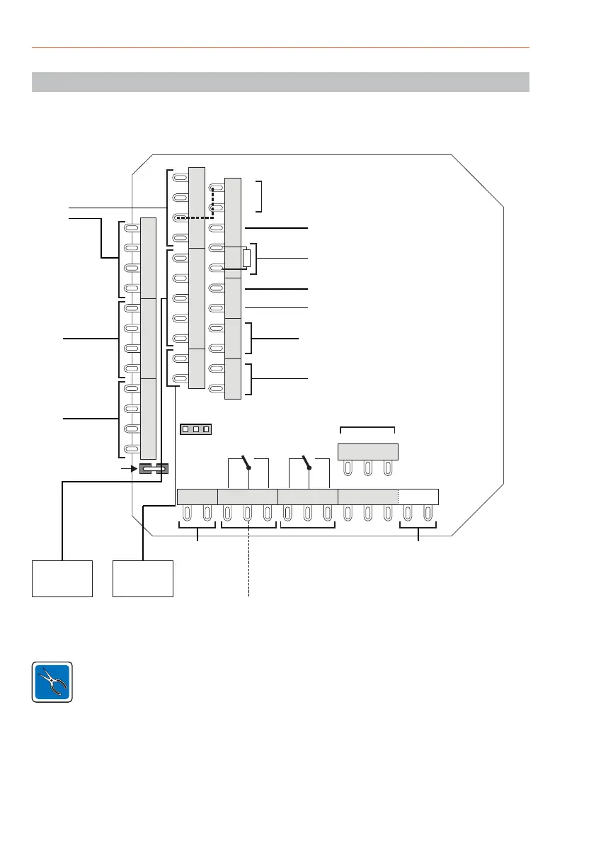
9.1 Terminal allocation - overview
The voltage for the blocking element and door strike
must always be supplied via U_ext.
ST23 ST11 ST12 ST13
ST18
ST21
ST3 ST20 ST10
ST9
RS-232
DB1
ST14
Cable shields e.g. U_ext.
Opening contact
Glass breakage
sensor
BUS-2
PC interface
Firmware update
AC release button
Cover contact - external reader
12k1 EOL if not used
IK2 operating unit or BL: Data / release
Bolt switching contact
Door strike armature contact
Presence control
SLIM-
LOCK
(1x)
RS-485
Readers
activ at
JP14 Pos. 2-3
semiconductor output
activ at JP14 Pos. 2-3
Rel 2
ZK Rel
Rel 1
S/US
NOC NOC
MM
NCC NCC
Rel 2Rel 1
Relay (Pos. 1-2)
Semiconductor output (Pos. 2-3)
JP14
1 2 3
ST2
D
0V
0V
+
closed
open
ST1
D
0V
0V
+
ST19
+
0V
D‘
SY
D
ST4
0V
MG
ST5
0V
MG
Acknowlegement signals - blocking element 1 / 3.
Attach bridge (see dashed line), if the inputs "Feedback
signals blocking element" are not being used.
9. Connection diagrams
 Loading...