56
Mounting and Connection Instructions IK3 Evaluation Unit BUS-2
9.5 Blocking elements
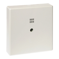
Electromechanical blocking elements can be used as an electromechanical locking mechanism (loc-
king device when system is armed). Following types are possible:
(Item no. 019030.20),
(Item no. 019033)
The evaluation unit monitors the bolt end position (Open/Closed). The acknowledgement signals of
the blocking element are evaluated. Monitoring affects the positive drive. If necessary, several bloc-
king elements can be used (switched parallel or cascaded, see Mounting and Connection Instruc-
tions of the blocking element).
Required software versions for monitoring the end position of the bolt:
- 561-MB8/16: From Version V06.xx onwards
- 561-MB100: From Version V06.xx onwards
- 561-HB48: From Version V07.xx onwards
- 561-MB256: From Version V04.xx onwards
- 561-MB256 plus: From Version V01.xx onwards
(Item no. 019032)
From the electrical point of view, blocking element 3 is identical with the blocking element 1 with a
magnetic contact (019033). The difference is the enhanced mechanical stability - no breaking point
at the locking bolt. VdS approval as final control element in access control systems (as per Class C).
(Item no. 019038, 019038.10)
The electronics for monitoring the end position of the bolt for the blocking element SLIM-LOCK are
located in the EU. Acknowledgement signals are not necessary.
An existing SLIM-LOCK is automatically identified when reset.
SLIM-LOCK can be used in addition to the blocking element 1 / 3.
Thanks to the compact, circular design, it is easy to install.
1.
a) The blocking element moves into end position "CLOSED". Positive drive condition is fulfilled.
Zone is armed
b) Blocking element does not move into end position "CLOSED". Positive drive condition is not fulfilled.
Zone is armed
Negative acknowledgement (approx. 1 min.). Fault LED at control panel with individual identifi-
cation (via LCD operating unit or control panel display).
The locking bolt is automatically retracted to the normal position.
- If the code carrier is re-read, the negative acknowledgement is stopped prematurely and the
control panel is ready for re-arming.
2.
a) The blocking element moves into end position "OPEN".
Zone is disarmed
b) Blocking element does not move into end position "OPEN".
Zone is disarmed; there is no acoustical fault indication.
Fault LED lights up; control panel is not ready to arm.
- If the code carrier is re-read, an attempt is made to move the bolt into the "OPEN" position. If
this attempt is successful, the control panel is ready to arm. If the bolt has still not reached the
end position "OPEN", the blocking element must be unlocked mechanically.
3.
Impending fault indicators can be cleared via "Clear detector groups” or function 201
(561-MB8/MB16/MB100/HB48) or function 203 (561-MB256).
9.5.1 Blocking element 1
Blocking element 1 MC
9.5.2 Blocking element 3
9.5.3 Blocking element SLIM-LOCK
9.5.4 Description of possible evaluation states and fault elimination
Due to the type of monitoring, the SLIM-LOCK can only be connected once.
not
Operation "Arm":
Operation "Disarm":
Clear impending fault indicators:
ª
ª
ª
ª
The fault indicator will be deleted automatically after the 2nd successful arming.
 Loading...
