50
Mounting and Connection Instructions IK3 Evaluation Unit BUS-2
A plug has been soldered to the cable of the operating unit at the factory especially for
test and premounting sets. For the final installation, it usually has to be cut off.
9.3.1 is
applicable.
An end of line resistor is not required at the user for
cable lengths £ Otherwise Chapter
The cable can be shortened as required.
:
The external source must provide the max. required current
to the reader (e.g. time-limited write/read mode incl. status
indication, possibly with background lighting).
6 m.
External voltage supply U_ext
Attention:
Do not confuse the data lines
A and B, otherwise the
device will not function!
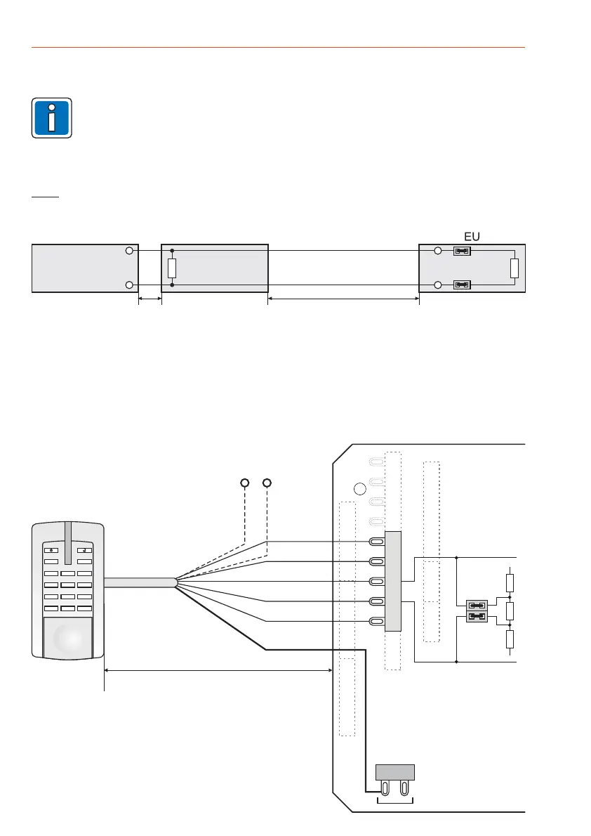
9.3.3 Direct connection to one reader
Possible types see 4.Chapter
ST5
ST4
Synch.
F I
2
3
6
5
4
789
3
0
r
1
RS-485
A(D)
B(D*)
ST1
ST10
ST9
ST2
120 W
+
JP15
ST19
ST21
ST23
ST20
6 m max.
EU
Cable shields
JP15 plugged:
120 EOL resistor
activated
W
Shield
red
blue
yellow
white
black
+U_BDT
12 V DC
0 V
0 V
+U_ext
9.3.2 Voltage supply of users (max. 4)
The at connection +U_BDT may not exceed .
Therefore can be directly supplied by the IK3 EU with 12 V DC via +U_BDT (reader
preferably in an unsecured area).
More readers must be supplied via an external source (e.g. U_ext from the control panel or a separate
power supply unit).
and must always be supplied
NOTE: total current consumption 200 mA
only one reader
AC readers Trafficpoint RS-485 externally.
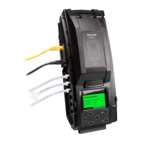
9.3.1 Line length and end of line resistors
The RS-485 bus line can be
The bus line must be closed with
up to 2000 m.
at both ends
total length
120
max. 6 m
of the
The distance between the distributor and the user should be
For users that have no connectable end of line resistor (e.g. "Accentic" readers), the resistor must be
installed in a distributor.
Note: W.
RS-485
Bus cable 2000 m max.
120 W120 W
A
B
RS-485 user
6 m max.
Distributor
JP15
JP15
A
B
9.3 Switching devices at Module bus/RS-485

 Loading...