63Mounting and Connection Instructions IK3 Evaluation Unit BUS-2
For all other connections
see Chapter 9
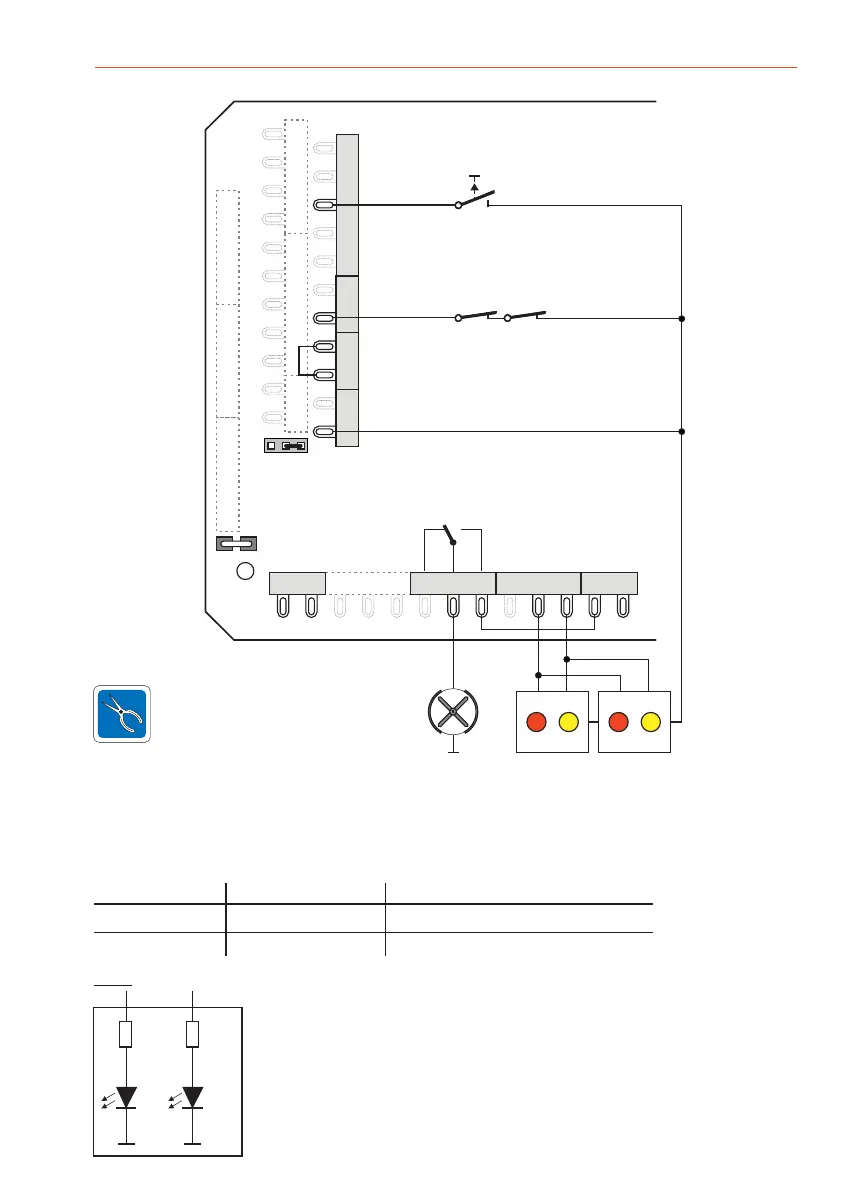
9.7.3 Status indication
Suggestion for indication with 2 LEDs:
Red: Other door open / release turnstile
Yellow: Manway occupied /turnstile/empty space occupied
Activation by other consumers:
Both of the outputs supply up to max. 50 mA at 12 V DC.
A free wheeling diode is required for inductive consumers (e.g. relay).
1k 1k
red yellow
Two operating states of the single access entry portal are indicated, either p
or turnstile:
Turnstile
Operating state 1 Other door open Release turnstile
ersonal interlock
Personal interlock
Operating state 2 Manway occupied Turnstile/empty space occupied
The status indication is not compulsory with the turnstileNote:
ST11 ST14
ST10
DB1
ST23 ST12 ST13
ST5
ST4
ST21
ST2
ST1
ST3
ST20
ST19
U_ext
+ 0V
Rel 2
0 V
Shield
Turnstile
release
Status indications
Turnstile is released
Data
Release
NC (normally closed contacts)
Presence-/empty space monitoring
EMERGENCY OPEN button
EU
NCC NOCM
Turnstile is occupied
ST9
 Loading...