- 9 -
2.6 Terminal Array
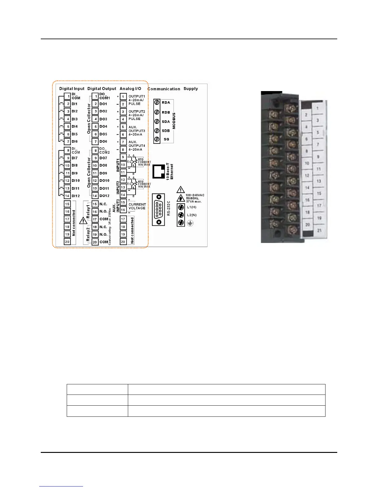
Wries are connected to the terminal base according to the layout , shown at left in Fig 2.5.2
Fig. 2.5.2 Terminal diagram label and Terminal Block style
Terminal Block Style
The terminal block is available in the barrier style, shown at right in Fig.2.5.2.
z Screw : M3.0
z Wire No. : #22 to 16AWG
Wiring Rules and Recommendations
In general, stranded copper wire should be used for non-thermocouple electrical connections.
Twisted-pair wiring with shielded cable will improve noise immunity if wire routing is suspect.
Wire Gage
The recommended minimum wire size for connections is as follows.
Wire Gauge Wire Application
20 DC current and voltage field wiring
22 DC current and voltage wiring in control room