- 51 -
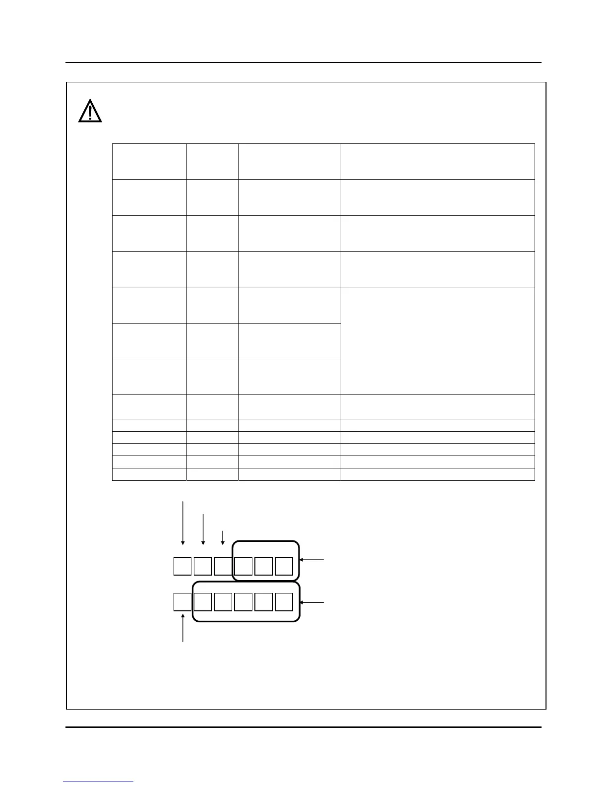
Example to arrange Events to Digital outputs
1. When Fix control and synchronous mode, if you need 3 Mode events (RUN, END, DOWN),
3 PV evnets (11,12, 21), and 1 Alarm event. You can arrange signals like below. And like
figure 3.10.1, the event part has to be set in Fix Set screen
.
Digital
input
terminal
EVENT
number
Description Set Items
1 42 RUN
Event number in Figure 3.12.1 : 42
Mode : RUN
Digital output number : 01
2 44 END
Event number in Figure 3.12.1 : 44
Mode : END
Digital output number : 02
3 51 DOWN
Event number in Figure 3.12.1 : 51
Mode : DOWN
Digital output number : 03
4 11
PV Event
PV/ABS/LOW(CH
1)
5 12
PV Event
PV/ABS/LOW(CH
2)
6 21
PV Event
SP/ABS/LOW(CH
1)
Set the event number like Figure 3.10.1
in Fix Set screen.(Refer to User manual)
7 70 Alarm
Event number in Figure 3.12.1: 70
Digital output number : 07
8 - Not used
9 - Not used
10 - Not used
11 - Not used
12 - Not used
Fig. 3.10.1 The part to arrange events to digital outputs on FIX SET screen of User Manual
X X X 21 26 27
X 0 0 0 0 0
1 2 3 4 5 6
7 8 9 10 11 12
RUN
END
DOWN
11th, 12th, 21th PV Event
70th Alarm signal
Events of digital output are not
assigned and the outputs are OFF.