- 58 -
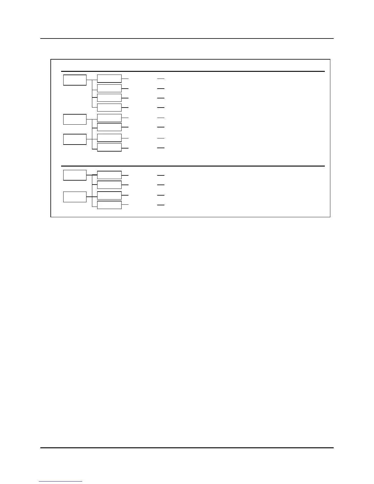
Table 3.12.1 Alarm Event Flowchart
(NOTE 1) When setting the Max/Min value, the Max value should be greater than the Min one.
(NOTE 2) See the table 3.12.2 in the next page for details on Alarm event On/Off operation algorithm.
For Type number in IPC5000S, it is available for odd number.
PV
11/12
PV-ABS-LOWCH1/CH2
13/14
PV-ABS-HIGHCH1/CH2
15/16
PV-DEV-LOWCH1/CH2
17/18
CH1/CH2
Measured
Value
Type Channel
Description OP point value
Differential
value
Delay Time
PV-DEV-LOW
SP
21/22
SP-ABS-LOWCH1/CH2
23/24
SP-ABS-HIGHCH1/CH2
25/26
SP-DEV-OFFCH1/CH2
27/28
CH1/CH2
Setting Value
SP-DEV-ON
DV
31/32
DV-DEV-OFFCH1/CH2
33/34
DV-DEV-ONCH1/CH2
Segment Target Value
MV
31/32 MV-ABS-LOWCH1/CH2
33/34
MV-ABS-HIGHCH1/CH2
Output Value
-19999~20000
-19999~20000
-19999~20000
-19999~20000
-19999~20000
-19999~20000
-19999~20000
-19999~20000
-19999~20000
-19999~20000
-5.0 ~ 105.0 %
-5.0 ~ 105.0 %
0~1000SPU
0~1000SPU
0~1000SPU
0~1000SPU
0~1000SPU
0~1000SPU
-19999~20000
-19999~20000
-19999~20000
-19999~20000
0.0 ~ 100.0 %
0.0 ~ 100.0 %
0~99sec
0~99sec
0~99sec
0~99sec
0~99sec
0~99sec
0~99sec
0~99sec
0~99sec
0~99sec
0~99sec
0~99sec
Target
Type Channel
Description Max Value Min Value Delay Time
Target
SP
Setting Value