- 35 -
3.4 PWM set Screen
You can assign the Pulse output source of IPC5000 and set the cycle time of the pulse in this
screen.
IPC5000 has four Pulse outputs(PW1,PW2,PW3,PW4) and they are used for Relay, Open
Collector and Voltage Pulse output. If the MV1, MV2, MV3 and MV4 are assigned, the Pulse is
operated according to the assigned MV output value. Refer to figure 3.4.1 for understanding.
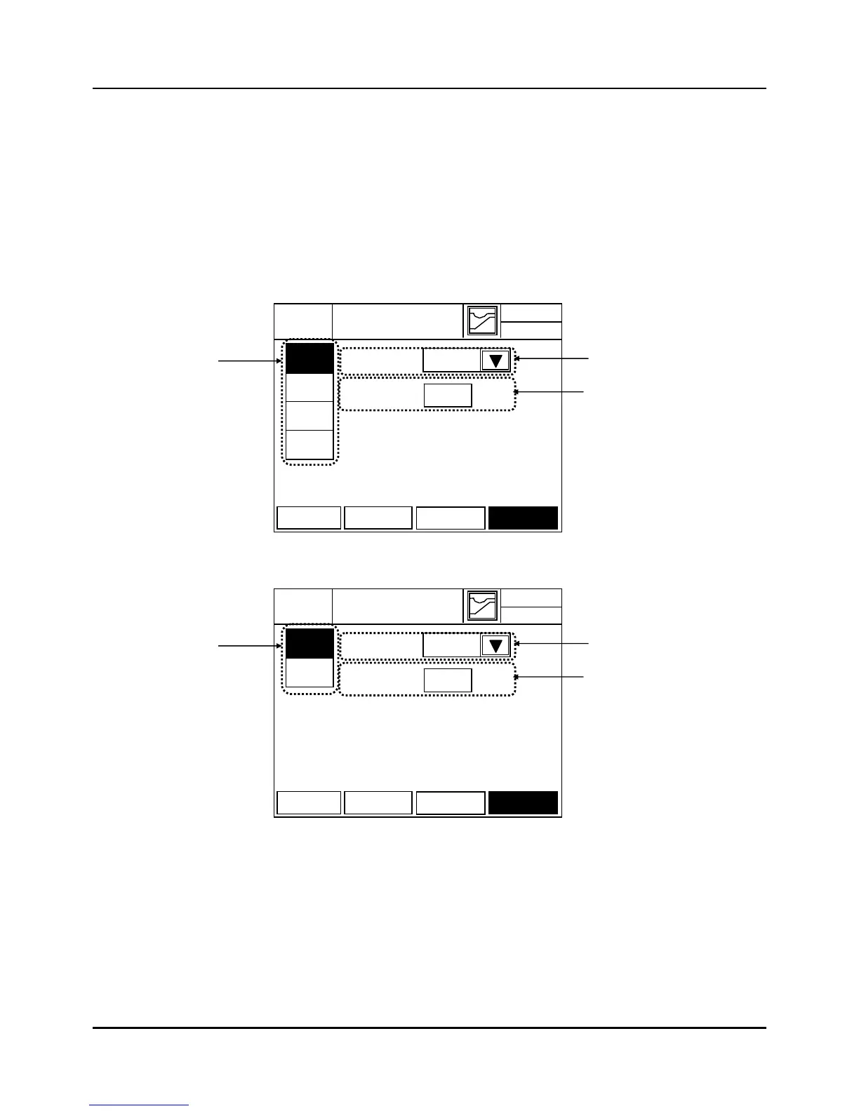
Assigning MVs to Pulse output is set in Figure 3.4.2.
(a) IPC5000D model
(b) IPS5000S model
Fig. 3.4.2 PWM SET screen-IPC5000S
(1) PWM(Pulse Width Modulation) Channel Assign button : it is highlighted and selected.
(2) Source set : It is combo box to assign the source(MV1,MV2,MV3 and MV4) for PWM.
If pushing the button(2), the combo box like figure 3.4.3 appears for the
output selection and the output for assigning can be set.
04-02.FRI
PWM SET
EXIT
14.38.33
PW1
(1)
PW2
SOURCE
MV1
PW3
PW4
AI SET DI/DO
AO SET
PWM SET
(2)
(3)
2
sec
CYCLE TIME
04-02.FRI
PWM SET
EXIT
14.38.33
PW1
(1)
PW2
SOURCE
MV1-H
AI SET DI/DO
AO SET
PWM SET
(2)
(3)
2
sec
CYCLE TIME