- 56 -
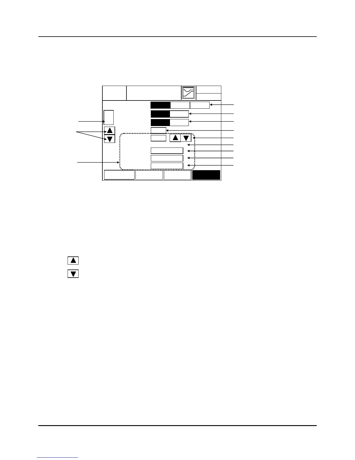
3.12 ALARM EVENT SET screen
ALARM: meter instrument warning
Fig. 3.12.1 ALARM SET screen
(1) EVENT No. Input and Display
z Type in the SIGNAL No to edit or configure. Then press ‘ENT’ button to move to the
corresponding signal No.
z Set Range: 61~80
(2) Changing EVENT No. for setup.
(3) ALARM TYPE: alarm type selection
z INNER : A Digital output operates according to inner data already set without assigning
event number. Or it is not necessary to assign digital output and event data in Fix set or
Program segment edition screen like PV or Time event. INNER type is same data with
event set of Fix set screen and the set part is same with (7) of figure 3.12.1.
z DIAGNOSIS: Triggered when in ‘PV Input Burn-out’ state. Set to MV OUPUT = 0.0%. If
the DIAGNOSIS is selected, (7) part of figure 3.12.1 disappears.
z FAIL: Triggered when SRAM, Flash Memory error, Program DATA error, initial operation
due to Power Failure, Auto-tuning fail, etc. occurs. If the FAIL is selected, (7) part of
figure 3.12.1 disappears.
( + ) Increase : Whenever this button is pushed, the event No. increases by one.
( - ) Decrease : Whenever this button is pushed, the event No. decreases by one.
61
01-23.TUE
EXIT
12. 59. 00
ALARM SET
PV