- 48 -
3.9 Compensation set screen
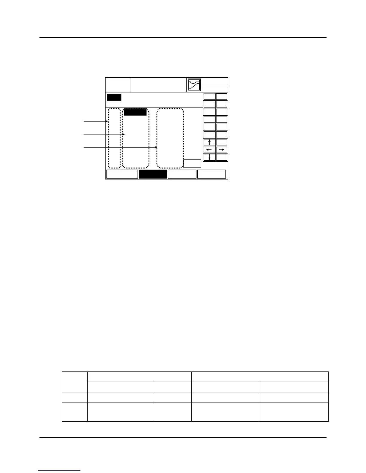
This screen comes from Fig 3.8.1
Fig. 3.9.1 Compensate set screen
(1) ITEM Number Display: displays up to 10
(2) CP set (Correction Point):
z Enters Correction Point input value at the specified item position. Typing in the input value
with the keypad on the left and pressing ‘ENT’ key changes and saves the value. ‘ESC’ key
cancels the process. Enter value in Engineering units. Also, input value can be moved with
the direction keys of the keypad on the right.
Range = -5.0% to 105.5% of PV input range
Default = 0
(3) BIAS (Enter value in Engineering units)
z Enters BIAS input standby status at the specified item position.
z Range
LIN Bias = -99.9 to +99.9
Default = Refer to Table 3.6.1
APPRX = -5.0% to 105.0% of input range
Default = Refer to Table 3.6.1
Table 3.6.1 Defaults of compensation
LIN. APPRX
No
CP set BIAS CP set BIAS
1 105% of Input range 0.0 -5% of Input range -5% of Input range
2~10 105% of Input range 0.0 105% of Input range 105% of Input range
2003.01.23
COMPENSATE
EXIT
12 H 59 M
ESC
―
0 1
2 3
4 5
6 7
8 9
.
ENT
No. BIAS DISPL