- 52 -
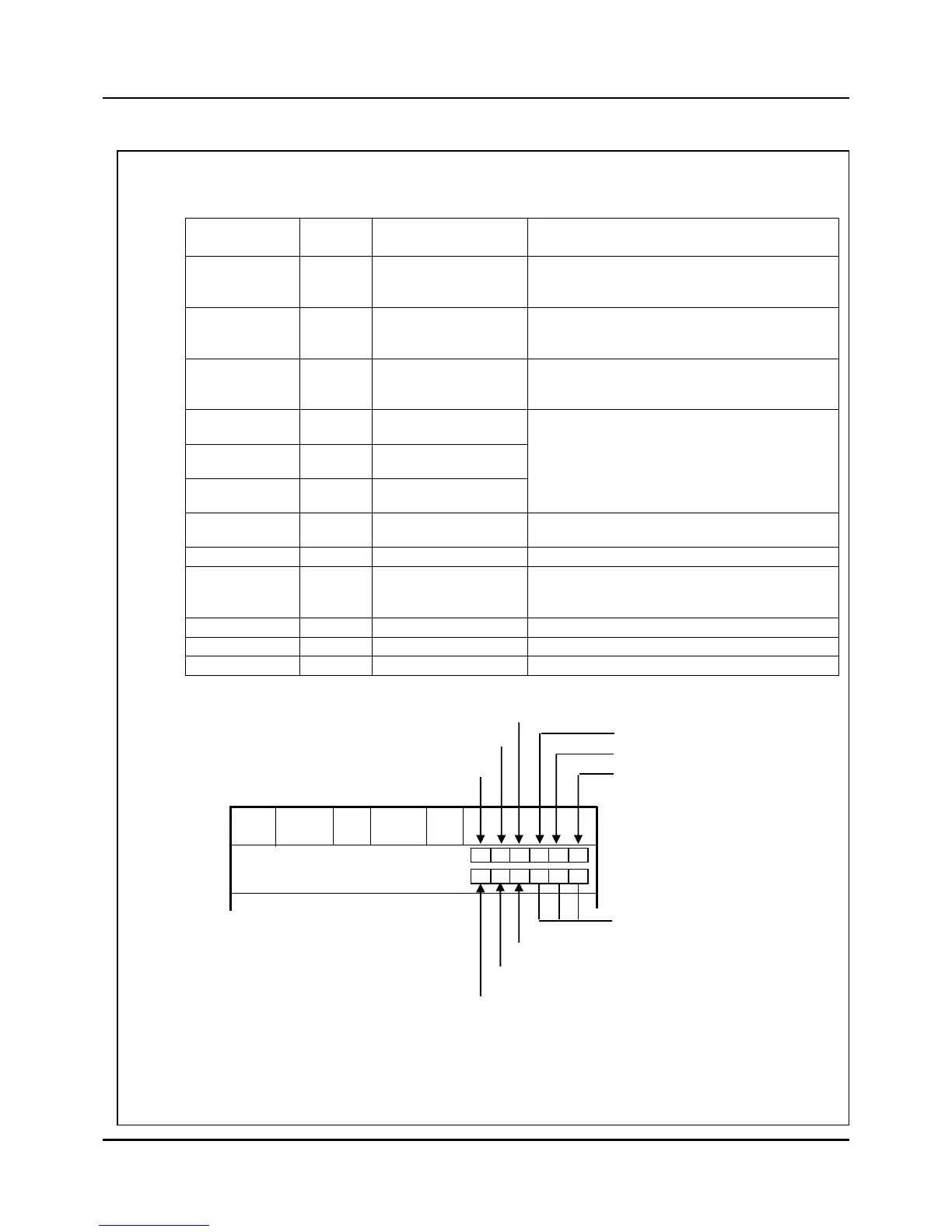
2. When Program control and Synchronous mode, if you need 3 mode events (RUN, END, DOWN), 3
PV events (21,26,27), 1 Alarm event (70), 2 Time Events (1,13), You can arrange the events like
below, in case that set them to segment No. 0 of program No. 0. And like Figure 3.10.2, the event
part has to be set in Segment Edit screen.
Digital
input terminal
Event
number
Description Set Items
1
42 RUN
Event number in Figure 3.12.1 : 42
Mode : RUN
Digital output number : 01
2
44 END
Event number in Figure 3.12.1 : 44
Mode : END
Digital output number : 02
3
51 DOWN
Event number in Figure 3.12.1 : 51
Mode : DOWN
Digital output number : 03
4
11
PV Event
PV/ABS/LOW(CH 1)
5
12
PV Event
PV/ABS/LOW(CH 2)
6
12
PV Event
SP/ABS/LOW(CH 1)
Set the event number in segment No. 0 of
program No. 0 like Figure 3.10.2 in Segment
Edit screen.(Refer to User manual)
Event numbers are equal to 12 but the OP
Point or Differential value can not same with
each other.
7
70 Alarm Event
Event number in Figure 3.12.1: 70
Digital output number : 07
8
1 ON Event
Event ON(Refer to User manual)
9
2 Time Event
Set the event number in segment No. 0 of
program No. 0 like Figure 3.10.2 in Segment
Edit screen.(Refer to User manual)
10 - Not used
11 - Not used
12 - Not used
Fig. 3.10.2 The part to arrange PV and Time events to digital outputs on SEG EDIT screen
of User Manual
70th Alarm Event
SEGMENTS
05
0
PROGRAM
000
M
1
00:20
50.0
PID
JC
TIME
SP
SEG
1
M M P P P
RUN
END
DOWN
11th PV Event
100.0
GS
0
EVENT SET
 Loading...


