- 27 -
3. Configuration
This is an initial set-up that determines appropriate control performance and capacity of
applied systems or devices and consists of the elements described on Fig. 3.1.1.
3.1 Screen configuration
Screen configuration consists of a screen switch selection mode (Fig. 3.1.1). To set up the
initial screen configuration (Fig. 3.2.1), press the right-hand corner at the bottom of the
main screen and then press the left-hand corner at the bottom of the screen (see Fig.
3.1.2).
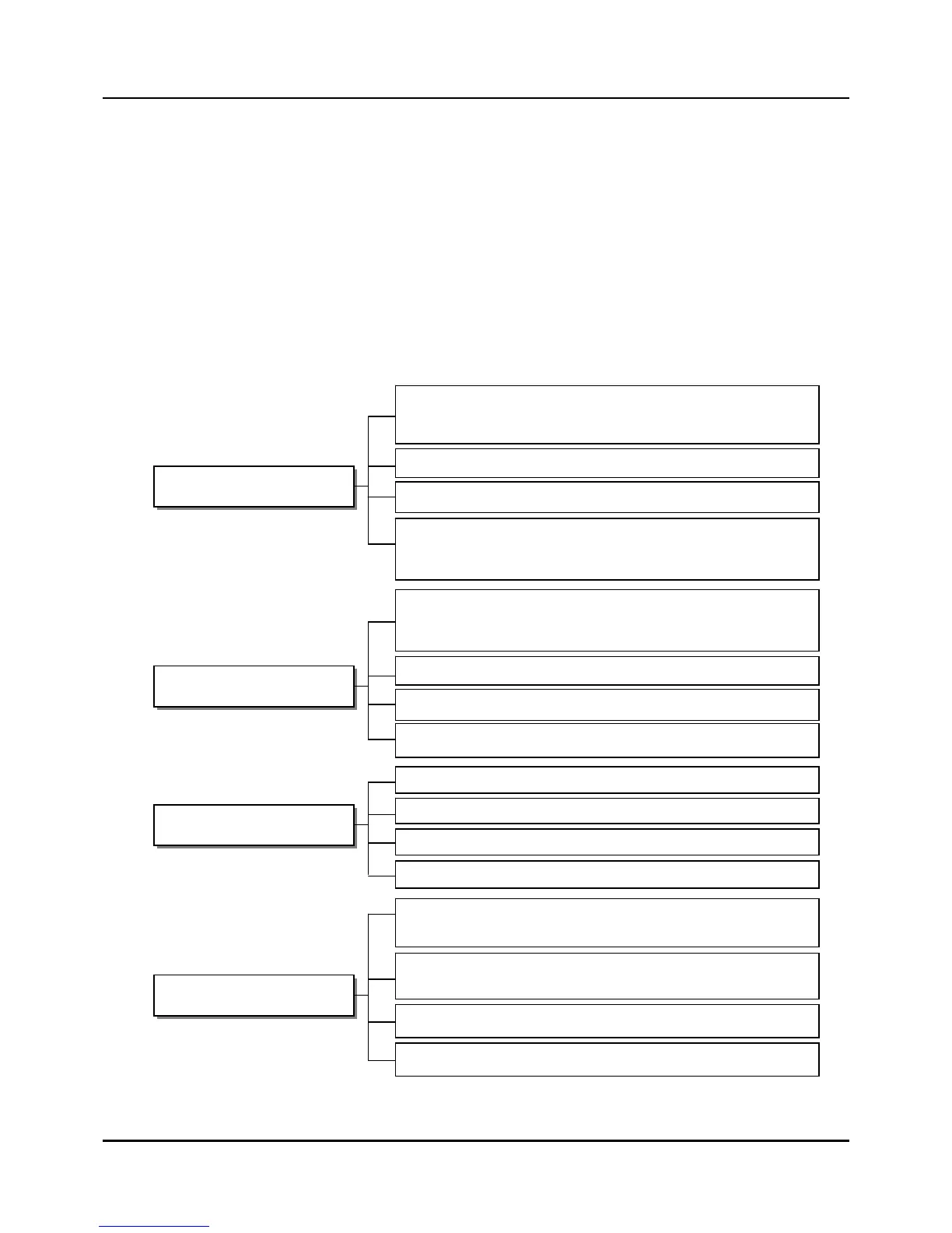
Fig. 3.1.1 Screen switch block
PID AND CONTROL SET
PID SET: Display and set-up of data related to PID control set
(PID-A/B and DUP-A/B, GAIN, Direction, Fuzzy OFF/ON, Failsafe)
PID VAL: Display and set-up of data related to PID constants
PID ZONE: Set-up of the PID zone
SYSTEM SET
SYS SET: Set-up of basic parts of IPC5000
(Asynchronous/Synchronous, Language, SP Tracking, Time unit,
Ram
Net Work: communication set-up
TROUBLE: Trouble message and Tune lock set-up
INITIAL: Data initializing, Version display
INPUT AND EVENT SET
RANGE: PV and SP ran
uare root and Low cut set-u
OFFSET: PV and SP offset set-u
ensate
Alarm event : Inner/Diagnos/Fail, Assigning channel, DO No., etc
AIO AND DIO SET
DI/DO : Monitoring the status of digital inputs and testing digital
outputs manually
AI SET: Set-up of analog input type, unit, decimal point, and scale for
linear input
AO SET: Set-up of analog output type and source
PWM SET: Set-up of source and period of Pulse Width Modulation
MODE event : Mode, Assinging channel, digital output number, etc
CONTROL: Set-up of Manual output condition and PID zone type
selection(Batch/Buples,Preset value, ZONE/SEG for PID group,
PV/SP for PID zone t